25.09.20-02.10.20
Maskin (Simen):
I finally got to see the 3d printed result, and started putting it together. For the split parts I decided to use some tape to hold them together, and for the axles, which I now see had too big of a size difference from the holes, I chose to tape them larger to add to the diameter and get a better fit.
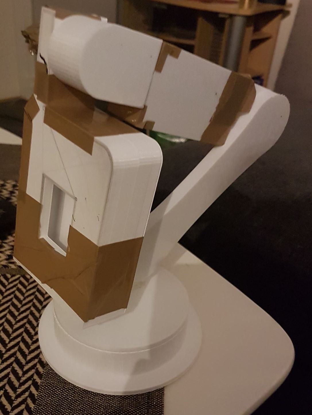
Now, yes, it does look ugly, but we remember the key mantra we chose to focus on last time: Function over Form. In addition, this is the first of several physical models we will acquire throughout this project.

Pick a card, this card
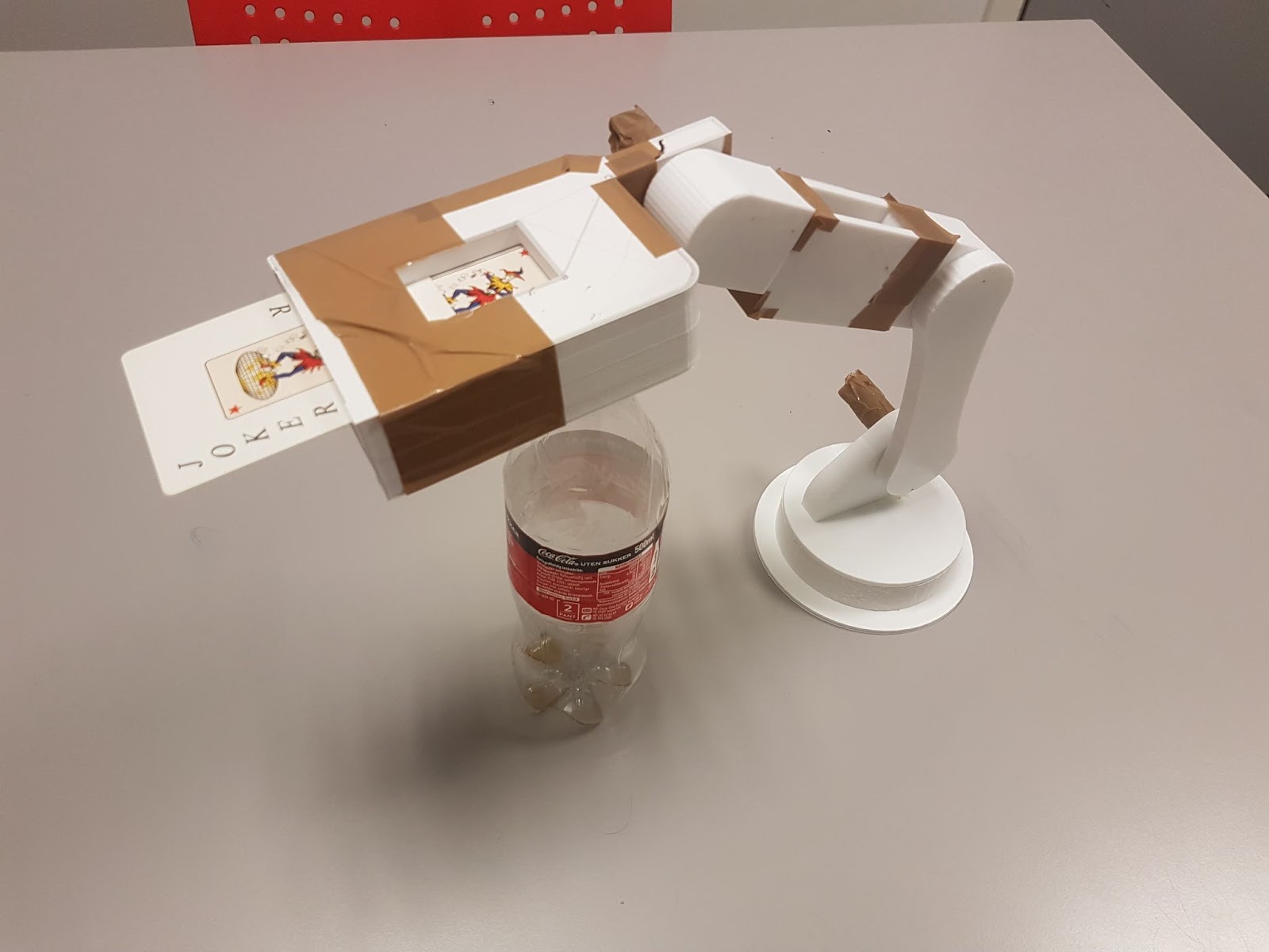
This model is not motorized in its joints, and cannot keep itself aloft. But, it can hold the cards, it has the mobility we want out of our arm, and it has the inherent ability of looking cool*.
*Subject to subjectivity.
In addition to this, we used the physical model to calculate some rough estimates of the weights and distances the servos will need to sustain and utilize to move this beast.
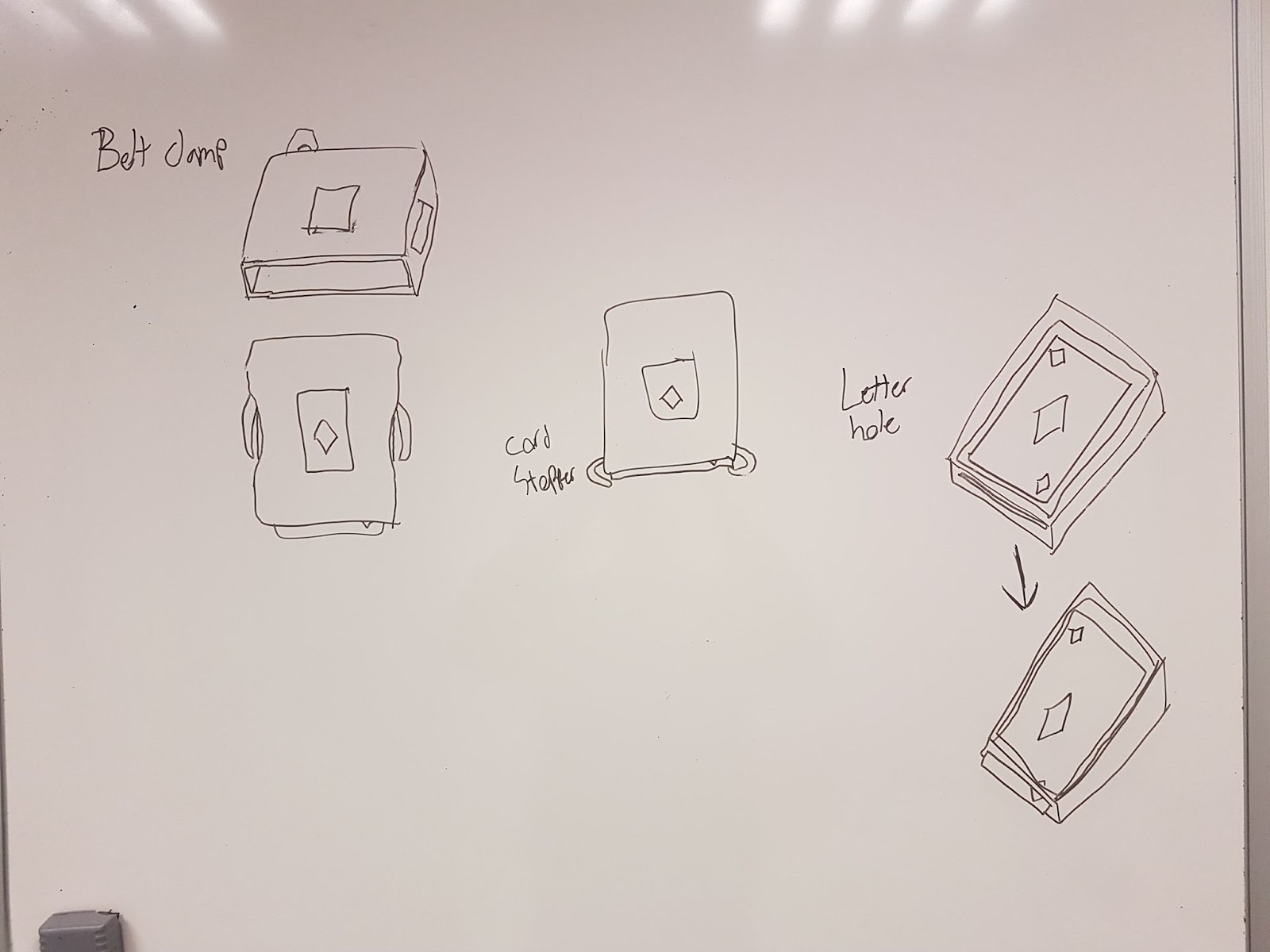
Onwards, in addition to making the parts “servo-friendly”, that is, changing the axles with servos outright, I will expand on the idea of cartridges in addition to the struggle of keeping the cards in the hand when challenging gravity (unless holstered they will simply fall out when the hand is at a downwards angle).
Elektro (Sondre):
Now that Simen has 3D printed the first version of the robotic arm and have calculated roughly how much torque we need from the motors, we are finally one step closer to connecting some motors on it to test the arm.
We had a group meeting this thursday, and Simen and I discussed which motors we will need and came to the conclusion that we’ll mostly need servo motors for the arm as of now, since most of the movement of the parts is limited to near 180 degrees, and they are precise as well as being able to deliver sufficient torque. While Simen did the calculations of the weight and such, I did some more research on how we’re going to power these motors. As expected, it is rather simple to do so. The plan is to provide the motors with an external power supply and to control them with the Raspberry Pi. The servos are controlled by a PWM signal which the Raspberry Pi has capabilities of doing, but if I understand it correctly, it is limited to only one PWM channel on the I/O ports. Thankfully, this can be solved by utilizing a PWM driver which we can connect to the Raspberry Pi, and I know that Danial has looked a bit into this, so I’m thinking that we can discuss this further next week.
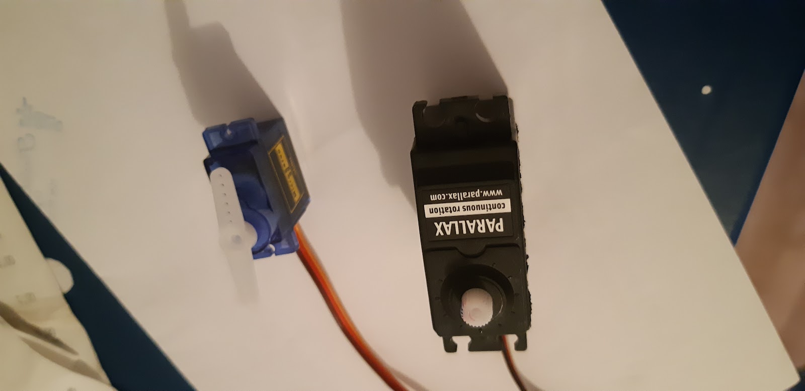
While on the subject of motors, our teacher Steven had a great lecture this week on sensors and actuators. I learned that it is possible to use an Arduino board to drive multiple motors with different PWM signals simultaneously on its I/O’s. I decided to test this in practice to get a hang of it, so I borrowed a few servo motors and used my Arduino mega to test them out. Pictured below are the motors that I borrowed.
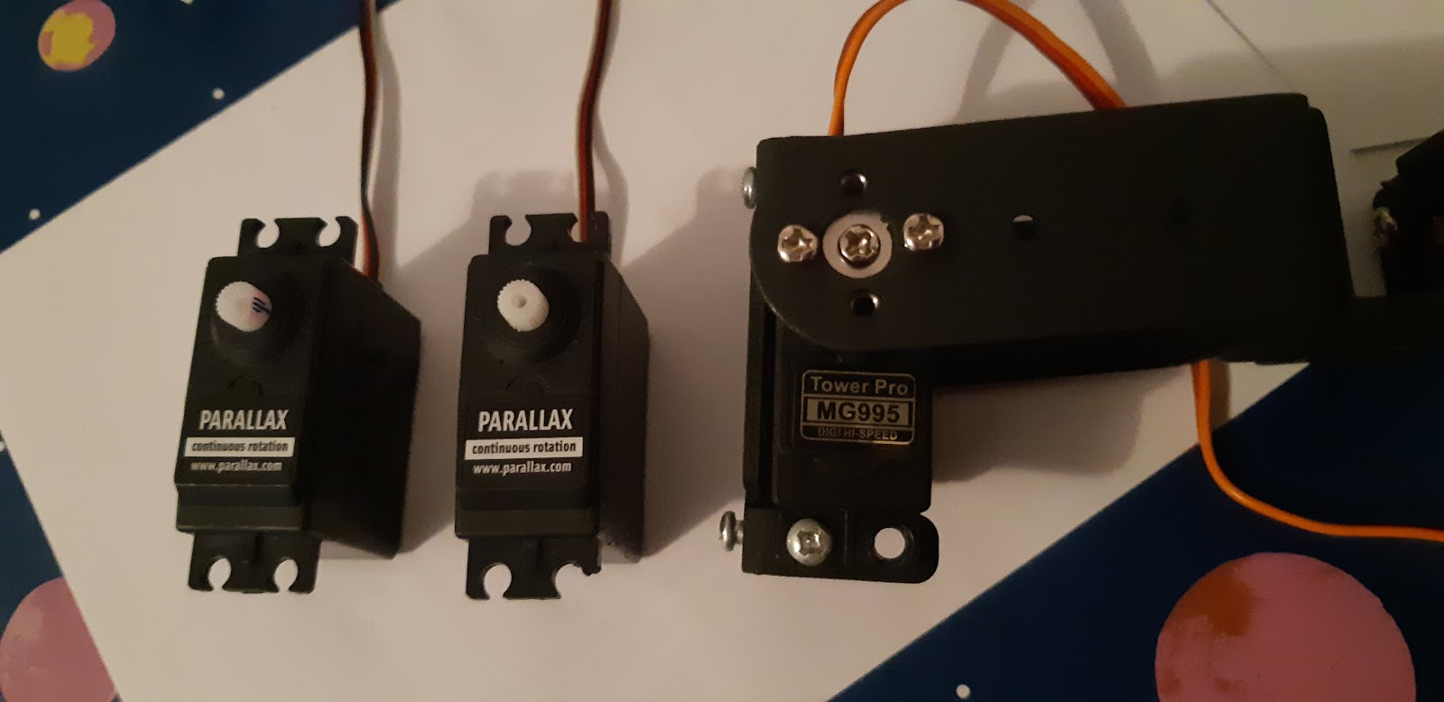
The Parallax motors are continuous rotation motors that can spin in both directions, and the Tower Pro is limited to 180 degrees.
I knew that the Arduino has a limited current output, so I needed to connect an external power supply to power the motors. I didn’t have one available at home, so my solution was to repurpose an old Micro USB charger by cutting off the tip and soldering on a couple of wires that I could connect to a breadboard.

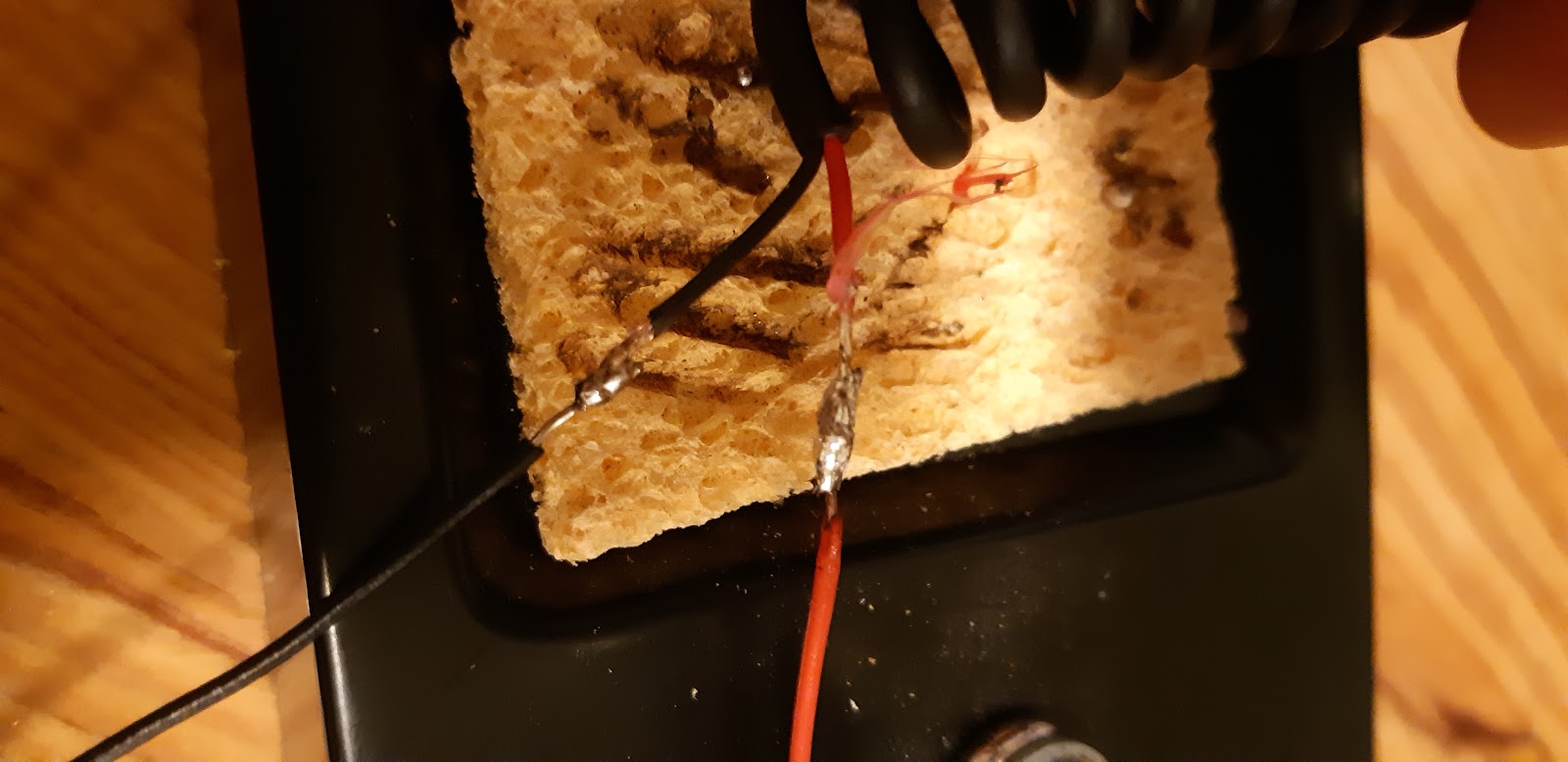

Since it’s only my second time soldering anything, the results weren’t pretty, but it did its job. Because there won’t be any large current running through the wires and this is a one time thing, I figured that securing the soldered wires with duct tape would be sufficient for this time. I connected the USB to an old cellphone charger and the wires on the breadboard. Now that I could test the motors, I only managed to get one of the continuous servo motors to work, and the Tower Pro motor only positioned itself in a certain angle and didn’t respond to any of the inputs that I tried to give it. I connected a potentiometer to the Arduino and used its value as the variable for input of the motors to check it more easily, but after struggling with the two motors for a while, I decided to use a micro servo motor that I already have instead.
When I used the potentiometer on the Parallex motor, I found out which values determine its rotation and idle state. I then connected both motors and wrote a simple program to run them both simultaneously, in which they both receive different PWM signals. You can click on the link below to see the test.
While this wasn’t exactly a crucial part of the development process, I feel that it was beneficial to do a test of running multiple motors, although it was just two motors for the moment. But now that I’ve got a grasp on how to run the motors, I hope that Simen and I can try to connect a few servos to the arm next week and to hopefully borrow some servos that meet our required specs, and to check the dimensions of these motors so that we can fit them properly on the arm. As mentioned earlier, I’ll also discuss the PWM driver with Danial in our next group meeting.
Data (Danial):
This sprint I have worked on with ROS, I have tried to get a better understanding of ROS and find out why I use the things I have chosen. I have also set up a folder (Hello_world) to see how ROS works and uses various commands. We bridge catkin over ros_build, the reason being that catkin is a newer and improved version of ros_build. Catkin is also more stable and also has Cmake integrated.
I also have the start Catkin and Roscore, which is the master node. I have done this by using 2 terminals in Ubuntu.

Data (Azim):
This week we had problems with the raspberry pi, more specifically we couldn’t get a visual from the raspberry pi. The signal was there but nothing was showing on the monitor. Thankfully, after some help from Stephen and a bit of craftiness, we learned that the issue was with the HDMI-adapter, and that it needed to be replaced.

Furthermore, this week I handed over the raspberry pi to Bjørnar this sprint because he needed it to debug his Bluetooth connection problem. My focus this week was therefore on the Pythons script that will isolate the rank and suit from a set of cards. Initially the algorithm of processing the playing cards would be split into two parts, detection and identification, but after we made a design choice where the camera module would be placed on the robot dealer and that a single card would be processed before ever touching the playing table, then the algorithm only needs to identify and separate the suit from the rank. Luckily, I found a tutorial to help me understand how to use the image processing functions in OpenCV, making my job easier.

How the algorithm works:
- Take a snippet of the corner where you have the rank and suit

- Zoom in by a factor of 4

- Threshold the image, this is a way of partitioning an image into a foreground and background, and it isolates objects by converting grayscale images into binary images.

- Cut into top (rank) and bottom (suit) half

- To isolate the rank, the program finds the contours in the top half, the rank will be snipped using the minimal area bounding rectangle for the largest contour. Then the snipped image is sized to for example 70×120 pixels

- Now that the rank is isolated it can be compared to the pre identified images that I have labeled myself. These images are referred to as the trained images and the isolated rank is the query image.
- To identify the rank, the query image is compared to each of the trained images by comparing the number of white pixels. The program counts how many white pixels are in the image and so a high number indicates a poor match, while a low number indicates a good match. The algorithm continues to compare with the training images until it achieves the “best match”. The same process is used to identify the suit of the card.

Continuing my work til next sprint, I will try to finish the different scripts as soon as possible so we can do proper testing with raspberry pi and the camera module.
References I used to understand image processing with OpenCV:
https://docs.opencv.org/3.4/d4/d73/tutorial_py_contours_begin.html
https://github.com/EdjeElectronics/OpenCV-Playing-Card-Detector
Data (Bjørnar):
This week was like the last one quite frustrating at times. This week i started by completely recreating the bluetooth application. The way i tried to communicate would simply not work, so with help from Steven we decided that using bluetooth low energy (BLE) would probably be simpler. I downloaded the BLE and MvmmCross packages in Visual Studio with NuGet but also here ran into multiple problems with package compatibility. There are some packages that are no longer supported and I therefore need to write code from scratch since all the examples used older versions that will no longer compile. I am currently stuck on this step but assume i will fix the errors before the next group session.
I took a pause from the app as i needed to learn how to train a neural network as i was the only group member with a powerful Nvidia GPU that supports CUDA. Getting the software for this was as always time consuming. I needed new graphics drivers, CUDA software and tensorflow. I used many hours to get everything ready to gather training data, but i found out that the .xml files that belong to each image were in the wrong format. When i tried to convert them to an excel file with a script the output was wrong. Since the training itself also takes many hours I had to continue this another day, but I made a lot of progress and believe we are closer than ever to training our robot.
To recap my week I again have very little to show for it, but i have no doubt put in many hours and hope the progress suddenly will show.