Date: 21.11.2019 – 03.12.2019 (final sprint)
GitHub: https://github.com/Bunogi/asd
The final week was a race to the finish in order to complete as much of the drone as we could before the deadline. We had multiple bottlenecks last week and we are happy to announce that we have overcome the obstacles and achieved a lot this week.
We finally managed to arm all four motors using the RC controller, as we had some issues with the flight controller calibration. Even though we have been able to arm a single or dual motors before, which we previously presented in a video, we never got to the point where all four motors worked together, due to the fact that the flight controller would not calibrate properly and therefore not agree to arm the motors for security purposes.
After spending many days on solving this matter, we finally got the flight controller calibrated properly and it is now up and running.
After reaching this great milestone, we got the PWM-board wired up with the flight controller to replace the manual RC controller with pure software. This is necessary in order to control the drone with our code and to implement our autonomous systems. Without this achievement, we would need to fly our drone with an RC controller and therefore prevent our software from interacting with the flight controller, which means that basically any sensors attached to the drone would not be able to command the drone to maneuver anywhere or take control of the drone itself. Luckily we found a way to achieve this and thereby solved the problem.

Since we had to leave the RC controller and rather replace it with pure software, this meant setting up a joystick ROS driver which allows us to read joystick events from anywhere in the system. The messages sent explain the input. For example, we have mapped a button to arming the motors. We set the button of the message to a predefined constant “BUTTON_ARM” to achieve this. This means that all consumers of the message can use it very easily without thinking about which button it actually maps to.
In order to convert the joystick input into input for the flight controller, we’re using a library which utilizes our PWM board. It acts exactly like the normal RC controller receiver would, except that it is generated from a separate location. This process of sending controller input across the system does cause some delay, but considering the RC controller runs on a 2.4GHz signal just like most WiFi, the delay is nowhere near as bad as we thought.
We also were able to set up the object detection part, using the YOLO algorithm with the COCO dataset. It’s not much, but it’s what we ended up having time for after prioritizing other things. It’s a base which can theoretically be built upon later. There’s no chance it will run on the Raspberry Pi, considering one of our laptops with a Ryzen 7 3700U with 8 threads manages a measly few frames per second. Therefore we have to run it on a laptop, but because we’re using ROS it’s effortless to move it there.
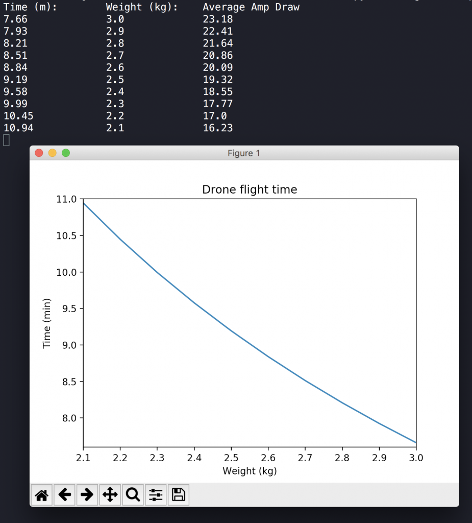
Before the actual test flight, we had to do some calculations to ensure that our drone weight is still within the limit, since we have a weight budget. It turns out that we gain a few minutes of flight time if we cut some weight, such as the powerbank, which of course is positive. Even thought our goal is not to reach a high amount of flight time, it would be nice to actually fly for a reasonable amount of time before we need to recharge the batteries. The simulation was written in Python.
Since we removed the Arduino board from our system, we had to rewrite the ultrasonic distance sensor code to run on the Raspberry Pi instead. We wrote the distance sensor code in C++ first, but it would not work properly and it gave us random results. We then wrote the code in Python and it worked fine. The distance sensor is a ROS node that calculates the distance down to the ground, and this given distance will also trigger the landing gear if the drone is close to the ground.
It turns out that the ultrasonic sensor sends out a 5V signal and the Raspberry Pi can only a 3.3V signal at input. Therefore we had to make a voltage divider to reduce the 5V signal down to 3.3V, to ensure that the Raspberry Pi does not get damaged. We found out that we need two resistors to achieve this and we soldered these cables together.


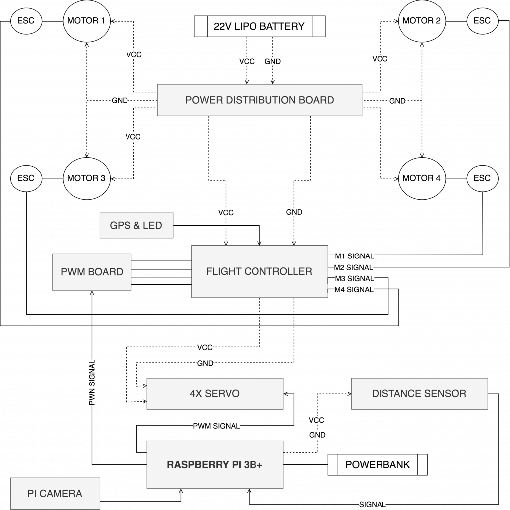
The diagram below shows our main components and how these are connected together, along with the electrical circuits.
Since we have just a few days left, we have figured out that we can show how the design of the chassis and the legs work. This is because there is just a few days left and no redesign will take place.
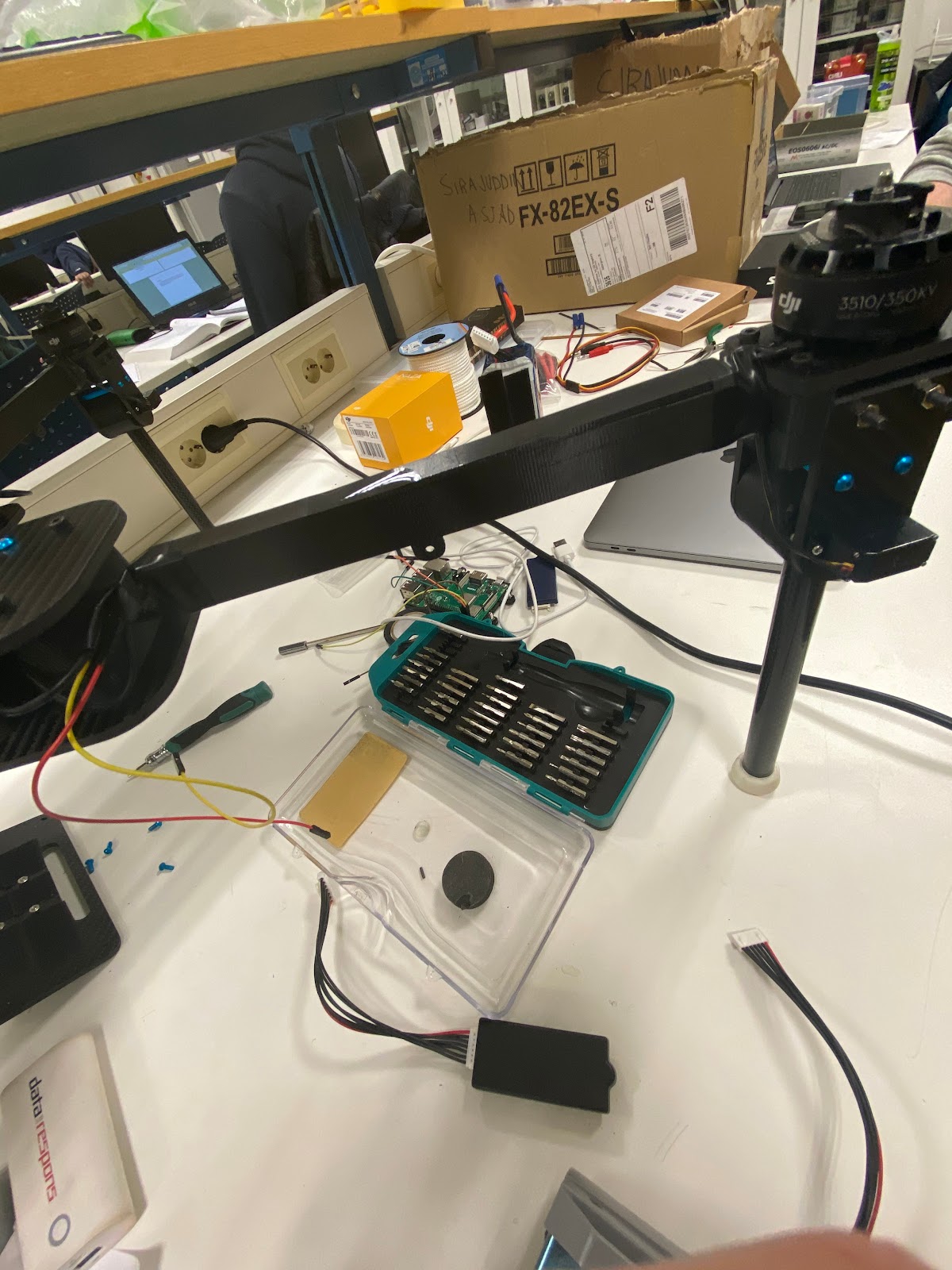
When it came to the mechanical part of the project the last couple of days, we have spent the days trying to finish up the design. This included things such as cable-management and hiding unnecessary disturbing elements both when it came to moving components (propellers etc.) and being disturbing in terms of the design. We have 3D-printed covers for the cables which goes from the motors to the speed controllers and stripped cables that were either too long or did not fit. We knew that the flight controller needed to be tight with no room for movement. We also knew that we wanted it to be as close to the center of gravity as possible. This is because it is very sensitive, but we could not find a fitting place for it, until this week. We managed to 3D-print a cover which was suitable just by drilling a few more skrewholes.

Along the way of making the drone, we have always been hopeful of just having one source of power which was the Li-Po battery. This has been proven to be a hard task, because of the differences between the individual components in terms of voltage and amperes. We are still hopeful of making this possible until friday, but we bought a powerbank to power Raspberry Pi and 3D-printed a cover for it, just in case. The powerbank solution was a bit disappointing for us, since we like the design so much and felt that the powerbank was hugely degrading the design that we have been working so hard to maintain. The powerbank is also quite heavy, but we still think that we are way below the weight-requirements, so we do not consider this as a problem. The only powerbank that we could get before the deadline of the project that gave us 3 amperes and 5 volts, which is required to power Raspberry Pi, was this one.

Every cable has been connected to where it belongs and the motors have been tested successfully. We have a few issues regarding one motor which will not arm every time we ask for it, but it will after a few power cycles, which we find to be very strange. After a bit of research we saw a few different scenarios that could cause this to happen. We tried to switch around the motors that the flight controller perceived as motor one and two, to check if there was something wrong with either the connection, speed controllers or even the motor itself, but with no luck. We even tried to change the screws, which is holding the motor, since we saw a recommendation of this online. We might want to do further research until friday, but we do not consider this as a major problem due to the fast approaching deadline.
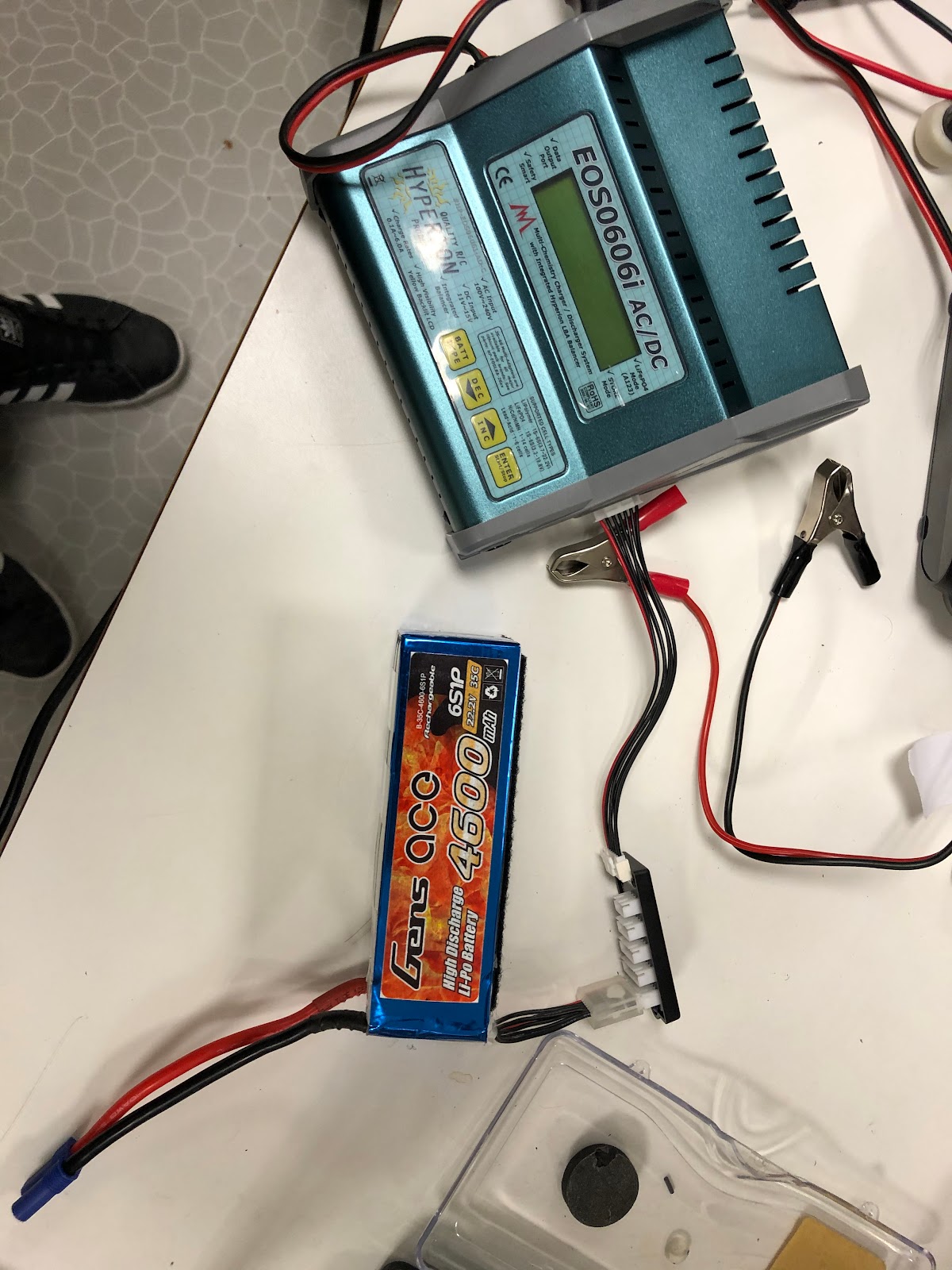
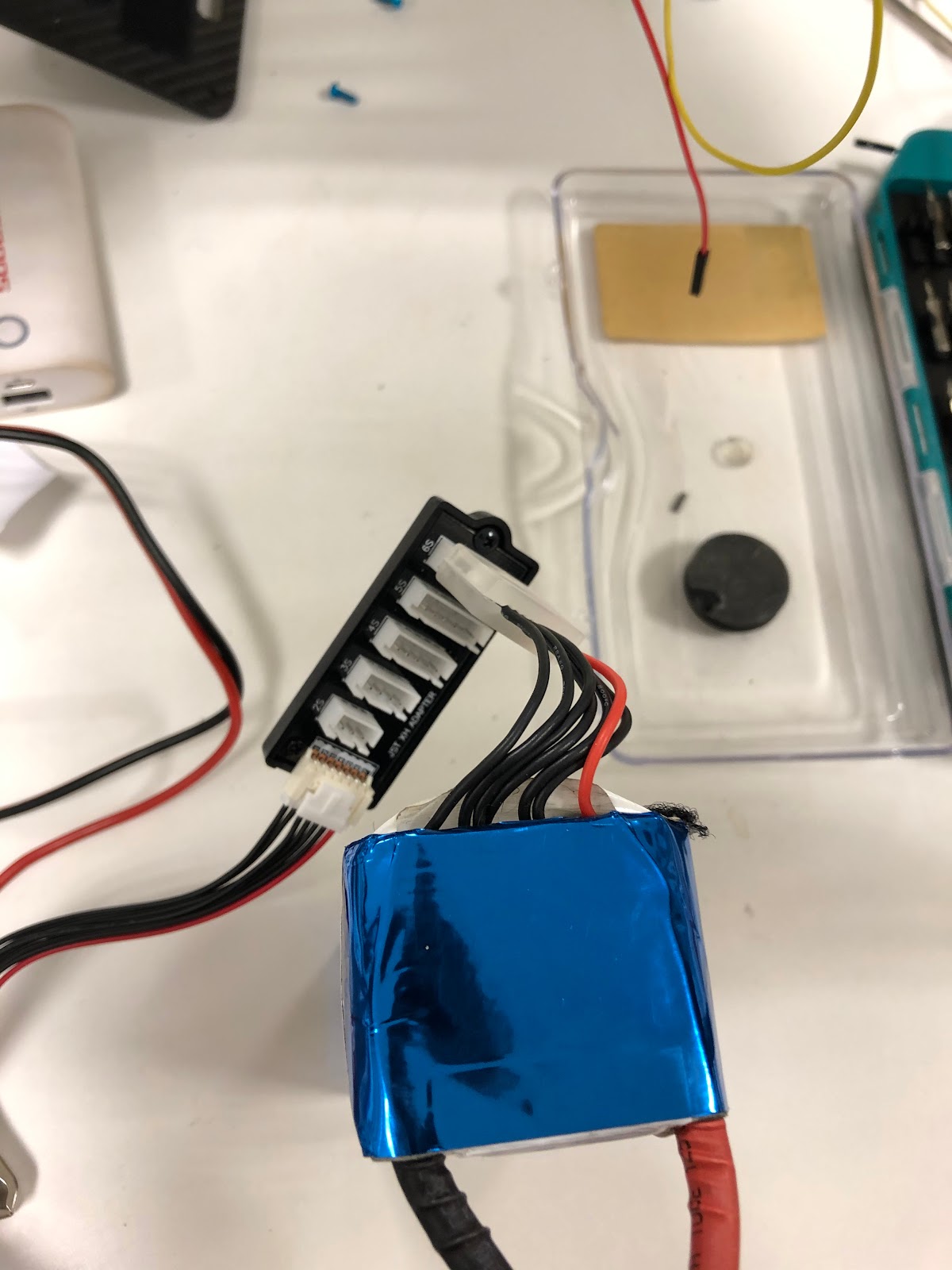
After the calibration and testing of the motors, which drained the battery in the process, a new problem occurred. The charging process of the Li-Po battery is not working as it should. After testing the drone together with software controls, we drained the batteries all the way down. This shouldn’t be a problem since you can just recharge them. However, as most other things on the drone, this would also be a bit of a struggle. To start off, the charger wouldn not work when we connected the power, so we tried to use another power supply, but this didn’t supply a high enough voltage. The next thing we tried was to change to another charger of the same kind. This time it started up when we connected the power. We connected the battery and plotted in correct settings. But again, new problems. Since this is a multicell battery, you need a special connection-cable to balance how much and to what cells the power will be distributed to. The problem is that the charger didn’t register that the cable was attached. We tried a few different solutions. Both different power supplies, different balance-cables etc. but still no luck. We concluded with trying a different battery, as the problem most likely was with the battery.
We also made a test rig for the flight-testing. This is because we want to test the steering of the drone, but not damage it if we crash it. It is basically a small deck with pillows attached to it. We will tie ropes to each arm of the drone and to the deck. This way the drone will only be allowed to go as high as we want to. And the pillows will most likely save some damage if something should fail. It is quite an easy setup, but it will work for this kind of testing.
Update 04/12-2019:
Alright, so we pulled some strings and got ahold of a new battery. The new battery is not as powerful as the old one, but it is enough to get the job done and we should get some flight time before we need to recharge the battery. We have tested the battery and it works fine with the drone, we are back on track and things are working again. Thanks to Joakim for helping us with the battery!
Since we got the battery working again, we were able to attach the drone onto the test rig to actually fly the drone. We spent some time recalibrating the motors, since everything is controlled through software, and finally got the drone up in the air.
We did some test flights to see how the drone operates in the air and it seems somewhat stable, yet there is room for improvement. The joystick on the controller is very sensitive, so it acts abruptly which might make it harder to control. We tied the drone with ropes to ensure that it does not fly into the roof or the walls, and we believe that the drone should stabilize itself better when it flies a little higher from the ground.
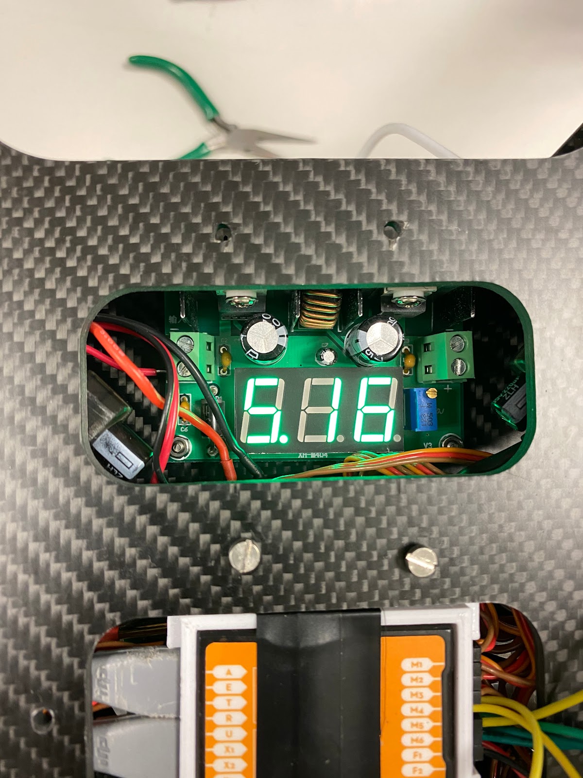
We also talked to Kåre and got ahold of a voltage transformer to transform 22V voltage from the LiPo battery to the 5V Raspberry Pi. Our current solution was to use a powerbank to supply power to the Raspberry Pi, and this looked really bad in terms of design and weight. The powerbank is quite bulky and heavy, and it would be very nice if we could get rid of it. Luckily we got ahold of a voltage transformer which means that we can supply power to all the drone components, including the Raspberry Pi from the same battery. There is a LED display on the transformer that shows the output voltage, which currently is locked at 5.1V.

That’s it for now! This project has been really fun and we have all learned incredibly much by working together, especially since we are a multidisciplinary group containing software and mechanical engineers. We have experienced many problems throughout the project, and luckily we have been able to tackle every single problem in one way or another.
And at last we want to thank Jan Dyre for loaning us expensive drone components and helping us throughout the project, and Kåre for helping our mechanical engineers with cutting the carbon fiber plates and much more! And of course, we want to thank Dag, Steven and Richard for all the guidelines throughout this project.
Thanks for an awesome semester!