- Joel Soto Escoda (Electro)
- Marius Kul Balsvik (Machine)
- Kristoffer Andersen (Machine)
- Steffen Barskrind (Computer)
- Kristian Meinich Backer-Owe (Computer)
- Nils Herman Lien Håre (Computer)
All of our code is on our Github page here https://github.com/steffenbk/Week-49-blog
NB! we added the new code for the IR remote after the deadline because our main controller died and we had to make a new one.
Machine:
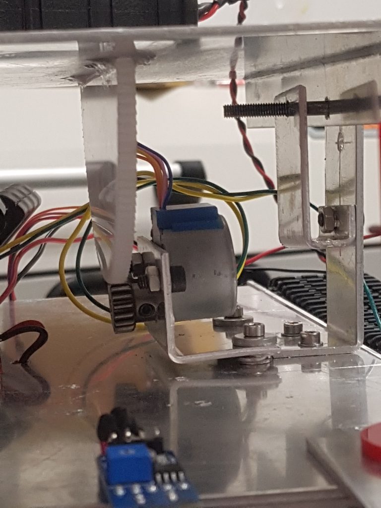
Perhaps the most nerve-wrecking thing in the project was seeing if the tilt-function would work as intended. We expected the teeth of the gears to mesh quite nicely but first we had to mount them. We made a bracket to hold the motor and knew that it was way easier to have to elevate the motor than to raise the top plate. You can see the washers raising the motor below. It looks like the laser cut gear is applying a lot of force downward and bending the bracket, but this isn’t the case as the bracket is not completely straight. The top gear is attached with glue.
Video of tilting the gun for the first time.
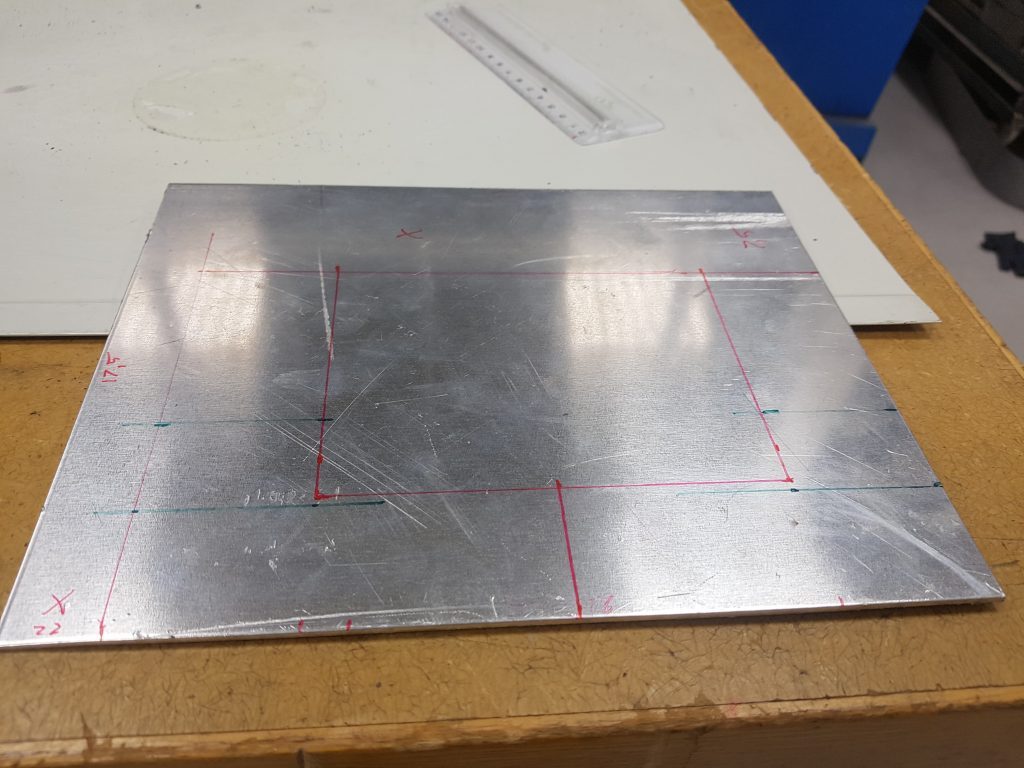
Because we don’t have a body for the tank we wanted to have atleast one part that makes it look cooler. A couple of front guards would not only make it look cooler but also help protect the front motors a little. The image above is a flat sheet with outlines in red and 45 degree bends in green.
This week became a bit of a roller coaster in the last day before the deadline for the final week, we had setup many things with the controllers that we bought, it was a PS2 wireless controller that got broken when we connected it to our battery, and it seems to have fried our receiver making the controller and the code for it useless as is. We need to figure out another way to get it up and running with either another receiver or create a new controller code of an IR sensor remote.
Computer:
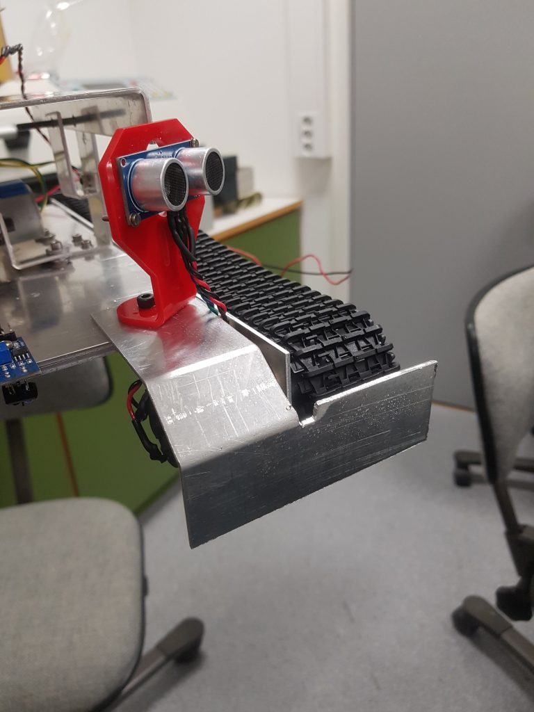
We’ve created a path following code for our tank, and it works by reading a path that i made my a tape line, and the sensors will follow the line until it comes to an end of a T-shaped line. So it makes a reading of the ground that we’ve yet to test since we just got most of the tank setup, but still haven’t tested all the features yet. So our focus now is to add all the code together and maybe make a whole new controller setup for our tank.

Figure 1: Path finding Sensor test

For the last two weeks, we have worked with making a new livestream camera application for our tanks. This because the arduino solution we had was not a practical one. Every time we wanted to start it up, we had to disconnect the ground. The solution we came up with, was to do the livestream with a Raspberry pi.
We borrowed a raspberry pi 1 with a raspberry camera v2. Downloaded the Rasbian lite(Only terminal) OS and flashed the image to a micro SD card, connected it to a monitor and fired the raspbian up. In the terminal, the following commands where given, sudo apt-get update && apt-get upgrade, to get let latest versions of the drivers and applications in the rasbian OS. Enabled the camera with sudo raspi-config and tried to test the image with raspistill -v -o test.jpg, this resulted in the error message “No data received from sensor” We went back to the drawing board, and tried the same process with a raspberry pi 3 b+, this we did not manage to get fired up. The reason could be that the read/write speed of the micro SD card was to low, but did not think of trying that, instead we bought a new raspberry 4 b+, a new SD card. Did all the things needed to get it up to date, connected the camera and tried the raspistill -v -o test.jpg again, and got the same error message. The camera was the problem, so went to Power, and got a new one. This time everything worked perfectly, and we were finally ready to implement the code that allow us to monitor and drive the tanks without seeing it. Below is a snippet of the python code.

We also made a program that will calculate the angle the gun will have to shoot at to hit it’s target. We made this in python, because the sensors on the tank only has a reach of 4 meters, so making arduino calculate the angle itself would not be of much use.

When you run the program you are prompted to type in the distance to the target. The program will then tell you what the optimal angle to shoot at is. If the target is beyond the reach of the tank, the program will tell you that the target is too far away, and what the maximum range is. Now we are looking away from wind/air resistance, so this will not be a 100% accurate, however it will be a good point to start firing from.


Electro:
Schematic
The previous image shows all the components that we have in our project. That components, previously, were studied and exposed separately trying to work in the small blocks/parts.
As the inputs, we can see that we have three ultrasonic sensors, two infrared sensors and two joysticks. The two joysticks are with what we’ve controlled everything until today but we’re going to implement a distant control without cables. As the outputs we can see two DC motors for driving motors and one stepper for the gun elevation. Finally, as our prototype is going to be without PC connection, we add the power supply of 8 AA batteries, in total 12 V.

Driving modes
At the end we created two codes. The first one called Motors_and_Joystick where we can make the full control of both driving motors with only one Joystick.
The second one called Motors_and_Sensors where the prototype can drive alone only reading what the ultrasonic sensors detect and then avoid the possible obstacles.
Airsoft gun
The Airsoft guns are replica toy weapons. They are a special type of very low-power smoothbore airguns designed to shoot non-metallic spherical projectiles often colloquially known as “BBs”. The projectiles are typically made of plastic or biodegradable resin materials. Airsoft gun power plants are designed to have low muzzle energy and the pellets have significantly less penetrative and stopping powers than conventional airgun. Although they are generally safe, we are using a gun. We need to take measures and be extremely careful.
Depending on the design mechanism for pellet propulsion, airsoft guns can be categorized into two groups. The first one, the mechanical, which consists of a coil spring-loaded piston air pump that is either manually cocked or in our case the automatically cycled by a battery-powered electric motor gearbox. The second one, the pneumatic, which operates by valve-controlled release of prefilled bottled gas such as “Green Gas” or CO2 canisters.
Trigger shooting
As we commented previously, in our case we have the electric motor gearbox gun. After the disassembly process, we were looking at different options to press the trigger and shoot. In the blog we post the button and servo solution but in the end it didn’t work. So, we decided to open the heart of the gun and luckily, we find that the gun trigger only was the switch between the battery and the air compressed motor. We extended the wires of the motor and we make holes outside the gun handle.

The previous image shows the cables going out of the handle. Connecting those two cables directly to the gun battery we saw that the gun fires, great! The next step was making the switch process electrically automatic. But, before, extend also the two battery wires.

The switch process between both components is going to be done with one relay. A relay is an electrically operated switch that can be turned on or off, letting the current go through or not, and can be controlled with low voltages, like the 5V provided by the Arduino pins. Controlling a relay module with the Arduino is as simple as controlling any other output. The following image shows the typical relay connection.

In our case, we’re going to connect the black cable of the gun with the black cable of the battery. The red cable of the gun is going to be connected in the NO and the red cable of the gun is going to be connected in the COM connection. With the previous connections when we’ll set the Arduino output to “1” the relay is going to switch from the NC (Normally Close connection) to the NO (Normally Open connection) closing our circuit and making the fire.
Trigger Elevation
The Gun is placed in one platform above the main vehicle chassis. That platform can bend down with gears. That gears are moved by one geared stepper motor. A stepper motor is a brushless DC electric motor that divides a full rotation into several equal steps. The motor’s position can then be commanded to move and hold at one of these steps without any position sensor for feedback. We thought that it was the best option to move the platform because we have the gun weight and because it’s easy to keep one position fix.
The stepper motor drive is done with his own driver. In the Gun_Inclination program file attached it’s written the Arduino program to control the motor with one joystick.