Electro:
Motors control
- Introduction
The tank driving system is only composed for two belts and in each belt, we’ve got one motor. Combining the two motors parameters we have the control to go forward, backward and make turns in both sides. As we commented previously, we’ll use 12 VDC/330 RPM motors. We can control the following motor parameters:
- Speed: controlling the motor input voltage that we give. The input is a PWM signal. It’s based in the average voltage and depends of the duty cycle. We can make that kind of control using a transistor.
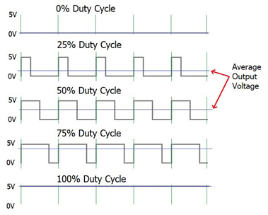
Figure 1: Example of PWM signal depending of the Duty Cycle
- Direction: inverting the current flow through the motor (change polarity). We can make it with the called H bridge circuit which has the motor in the middle.
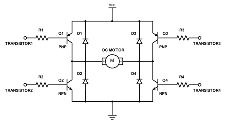
Figure 2: The H bridge connection
The L298N Driver is the perfect one. It can control the two previous variables together and it’s compatible with Arduino world.
- Technical part
The driver can control up to two motors, A and B. It receives the orders from the board by the inputs. In the inputs connections it has enable A and enable B with what we can control the PWM signal (Speed). Also, it has in 1 and in 2 for the Motor A rotation direction control. In the case of the motor B, in 3 and in 4 for the direction control.
| IN 1 | IN 2 | ||
| Motor A | Forward | 0 | 1 |
| Backward | 1 | 0 | |
| IN 3 | IN 4 | ||
| Motor B | Forward | 0 | 1 |
| Backward | 1 | 0 |
Figure 3: Motor direction table depending of the inputs
All the non-contemplated cases in the previous table will stop the motor. Following with the outputs, to control the Motor A it has out 1 and out 2. In case of the Motor B it has out 3 and out 4. The previous connections go directly to the motors. They give voltage and current depending of what we say to the driver.
Finally, in terms of power, the driver has the Vcc pin input that can be supplied between 5 to 35 V. Also, it has the GND pin and the +5V in/out pin which you can receive or give power depending of the jumper configuration.
- Driving modes
The main objective of the project is to interact with the outside world. But also, we know that the play station controller that we’ll use it has a lot of configurable buttons. So, we though and decided the option to use a few buttons for a few modes. However, we can divide the modes in manual and autonomous.
- Manual control
The manual control is basically a Master-Slave communication between the controller and the board so we’re going to have the full control in our hands. In this mode, we need to configure the motors to work according to the orders given by the joysticks. Each joystick has two potentiometers, one for each cartesian coordinate. We need to say that in the following test we made the motors full control with only one Joystick but maybe in the final prototype we’ll change it to two Joysticks, one for motor.
The joystick produces an analog value for each coordinate, x and y. To give the motor correct order we need to read the analog value. We’ve made a reading test with the Arduino Monitor Serie in each direction point and we fix the limits following the next picture.
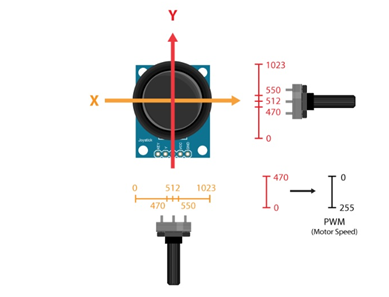
Figure 4: Joystick potentiometer limits
When we’ve got the directions clear, the next step is to convert the analog values of the center point to each direction in the correct speed signal range with the PWM. For example, from 550 to 1023 to 0-255. Following the previous step and the potentiometer limits we made a test program.
The program has the possible 5 cases of the 5 joystick positions. We fix a critic value for the analog reading to identify in what case we are. In every case, we define how each motor work related of the movement that we want to do. We’ve programed the turning trajectory with the opposite rotation of the motors but it’s possible to do it with the speed also.
(Add the video of the joystick driving)
- Autonomous control
In this mode, the main objective is to teach our system with the behavior that we want. It’s more delicate and difficult than the previous one because we are going to give the full control to the system.
The vehicle has 3 ultrasonic sensors and it’ll have 2 infrared ones. We’ll need to program the brain (board) to receive that inputs and act correctly. The work of the board after the input is known in which situation he is. Then only say to the motors what to do with the direction and speed. For example, in the test program that we made we’ve only considered two cases, left ultrasonic sensor detection and right ultrasonic sensor detection. We’ve programed our motors to go forward until any obstacle detection. Then when the sensor gives the critic distance value and depending on the side, the motors stop, wait and turn in the opposite direction of the detection. The previous example code was a way to use what we have in the lab before start with the prototype. In which we’ll have more cases with possible combinations between sensors.
(Add the video of the autonomous driving with the sensors)
Furthermore, as is know in the programming world there are no limits and everything it’s possible in part. For this, we’ve thought that apart of the 100% autonomous driving, it could be interesting other autonomous modes. For example, a straight-ahead trajectory or a round trajectory or also a fire trajectory with some military tactics.
Video:
https://drive.google.com/file/d/1pIrinFUn5nRQLuh_Gi_A_eJaLSgCtq_C/view?usp=sharing