Date: 07.11.2019 – 14.11.2019
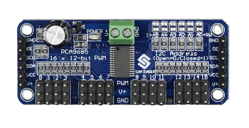
This week we found a hacky solution to our lack-of-API problem: there is a library for the Raspberry Pi out there which will simulate inputs to our flight controller. What this means is that we should be able to use that library in order to control our drone, salvaging the autonomous part of the project. It requires the purchase of a special PWM generator card, since the Raspberry Pi’s pins do not have enough hardware-accelerated PWM pins available to drive it. We hope to have the part as soon as possible in order to experiment.
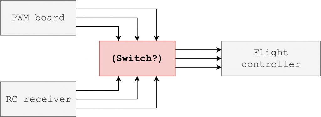
Since the goal is to make the drone communicate with our remote control center (software), along with a normal RC receiver (for security purposes), we could not figure out how we can make the flight controller receive inputs from both software and the radio controller. We talked to Jan Dyre since he’s quite experienced in this field, and he recommended us to create a kind of switch between the PWM board and the RC receiver to shift between the input signals, basically the same way a multiplexer works. Since we have no electrical engineer in our group, we had to do some research to learn how this is accomplishable, as this is a unique problem. The simple diagram below illustrates what we are trying to accomplish.
We had to rewrite parts of our code to accommodate using the Raspberry Pi camera on an actual Raspberry Pi. This requires the use of a special library, since it’s not simply exposed to userspace as a normal video device. The old setup was for the Nvidia Jetson Nano, where you access the camera using a gstreamer pipeline. We spent some time making these adjustments, but it finally works now.
In order to allow us to keep running the entire system on a single laptop, we check at compile-time for the processor architecture. If it’s arm7f, which is the Pi’s architecture, the Pi camera support is compiled in. Otherwise, we keep the old behaviour, where we open a video file declared in a ROS parameter.
We finally got the carbon fiber plates which was cut out with a CNC-mill. This made us able to put the final iteration of the drone together. Due to small tolerances when making the drone, we had to sand a few parts to make it fit the drone perfectly. We had to be very precise and doing this slow in order to get the wanted size of the different parts. We also had to drill up a few screw holes which was made with the CNC-mill.


We also had to redesign a little and make space for the speed controllers inside the main chassis instead of underneath the motors. We saw this as a safer solution so the speed controllers don’t get damaged in case of a crash. This made us able to put standoffs under the engines instead, which we also had to sand of a millimeter in order to make it fit. These standoffs are made of aluminium which can handle a bit of bending and stretching compared to the previous iteration which was made out of a carbon fiber plate which was holding the speed controllers. The first design was based on the fact that we didn’t need to extend the cables which are connecting the speed controllers and the motors. This design on the other hand, will force us to do this.
We also did some research on the Naza-M flight controller, because of some uncertainty on if this works as planned. The drone is ready for flying according to the program, but during a test on the motors, we could not get them to start revving. We will test further when the drone is completely mounted, as we are waiting for some special cables to arrive before we can fully mount the entire drone. If we can verify that the motors are rotating upon mounting the drone, there should be no problem implementing the autonomous part of our project, and to give commands to the drone through software.