Mechanical:
Several of the parts in our design are based on cutting, bending and drilling sheets of metal. This post will focus on bending.
When something is bent the inner side is compressed while the outer side undergoes tension. This changes the dimensions of the part and we have to account for this when planning the initial dimensions on our sheet. In other words we need to add extra length to allow for the bend to happen so that it won’t change the final dimensions. To figure out exactly how much we need to add, we can use the formula for “bend allowance”.

For this we need to determine some variables. B stands for “bend angle” and so far all our bends are 90 degree. IR stands for “inside radius” which is the radius made by the bend on the inside. MT means material thickness which is the thickness of the sheet we are using and K stands for k-factor, which is the ratio between the offset of the neutral axis from the inside bend and the material thickness when the metal is bent. This ratio depends on the material we are bending, the size of the inside radius, the material thickness and the method we use for bending. From this description we can see that the formula has variables that depend on each other. The internet had charts for rough values to use as the k-factor but I didn’t fully understand these and thought it could be interesting to calculate ourselves. By re-balancing the formula above we get this:

IR is now R and MT is now T. So to do this we would have to bend and do some measurements.

Starting with 3 samples that are as identical as possible. L: 100 mm W: 20 mm. Marked for bending at the middle.

All samples are bent and checked to be exactly 90 degrees. The flanges are then measured so that we get an average length of 52,58 mm.

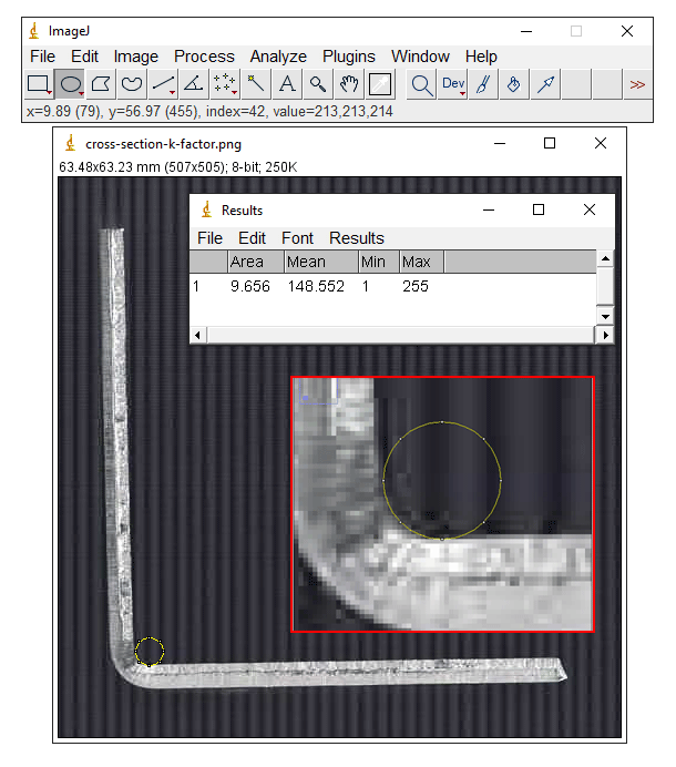
By scanning the parts in a copy machine and using image analyzing software (ImageJ) we could determine the size of the inner radius to be 1,75 mm.

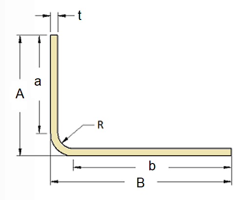
The last variable we need is the bend allowance. Because we now have all these measurements, BA is simply the initial length of our samples minus their legs “a” and “b”. And because we know the flanges, the material thickness and the radius the BA equals 4,95.

By plugging this into the formula we get the k-factor. Now that we have this value we can use it in Solidworks to make the dimensions as accurate as possible.
But say we didn’t do this, would it matter if a measurement on a part were off by a couple of millimeters in this project? Not really, but we’ll try to do it as precise as we know how.