Date: 12.09.2019 – 19.09.2019
This week started with getting the software components in place. We installed Ubuntu on the Nvidia Jetson Nano and experimented with its functionalities by implementing the Raspberry Pi Camera on it. We started by adding nodes to the ROS network and wrote some code to publish images from the camera to the network, along with setting up a live video feed. We experienced some minor issues when we tried to read data from the camera, which we are hoping to resolve within the upcoming week.
The next phase of our software development is to set up a neural network running the image recognition. The camera node will capture video and send this data to the machine learning node, which will analyze the images and at last publish the results.
The best way to transfer images over the ROS network is by using a library called “ROS Image Transport”. It allows you to transport images in a variety of ways, such as efficient streaming video or a stream of PNGs. You simply subscribe to a topic using a handle to an image transport instance as opposed to a normal ROS node handle, and receive raw image data. There is a slight problem though: it does not work with Python. While ROS allows you to write nodes in a multitude of languages and integrate them with the build system, image transport simply is not available. Our fix is to write a node in C++ using the Python library instead. This will allow us to evaluate and run Python code within our C++ node. That way we can receive images using image transport, run them through our machine learning model, and then publish the results.
Our system contains multiple subsystems and we have divided some subsystems into software components. Since we are two software engineers working on this system, it is easy to assign tasks and work on different modules when we have different software components that needs to be developed.
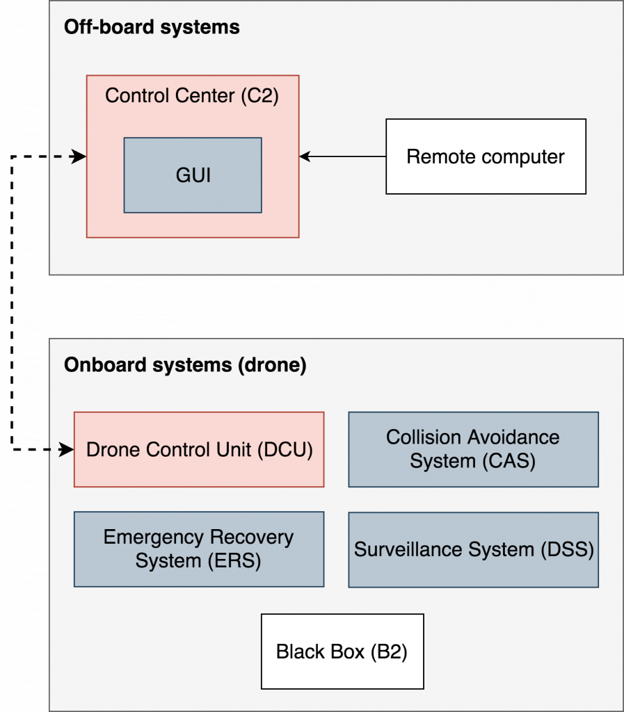
Some of our software components are (R: red, Y: yellow, G: green):
- Control Center (C2):
- [R] Send messages to the drone with maneuverability information.
- [R] Ensure a real-time connection with the drone through a heartbeat system.
- GUI:
- [Y] Designate commands to the drone.
- [R] Show a list of objects that have been detected.
- [Y] Show an interface to assign flight location.
- [G] Show drone position in a tracking system using 3D-rendering.
- [Y] Show live video feed with and without detection boxes.
- Drone Control Unit (DCU):
- [R] Communicate with the flight controller.
- [R] Ensure that the drone is stabilized at all times.
- [R] Receive manual control instructions from user.
- [Y] Receive and perform maneuverability requests from C2.
- Surveillance System (DSS):
- [R] Receive specific surveillance commands from C2.
- [R] Detect specific and nonspecific objects in the environment.
- [R] Capture images and report back to C2.
- [Y] Frequently send logs to C2 for data analysis. Motor speed, temperature, etc.
- Collision Avoidance System (CAS):
- [R] Use IR-sensors to detect close objects (walls).
- [R] Overtake drone control to avoid collisions.
- Emergency Recovery System (ERS):
- [R] Trigger a backup plan during connection loss.
- [R] Focus on keeping the drone alive, perhaps perform an emergency landing.
- [R] Save all logs to the Black Box.
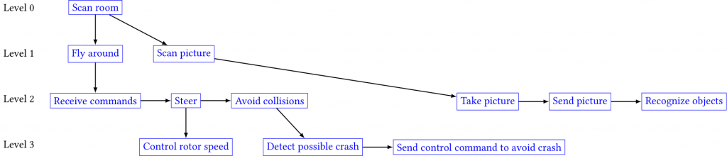
In order to briefly describe the functionality of our drone, we made a functional block diagram to indicate its behaviour, divided into several levels of depth. Even though this diagram is created from an abstract level of view, it is enough to define the main purpose of our system to anyone who might be interested in our product. In the diagram below we are focusing on the surveillance aspect of our system, as this is our main focus as well.
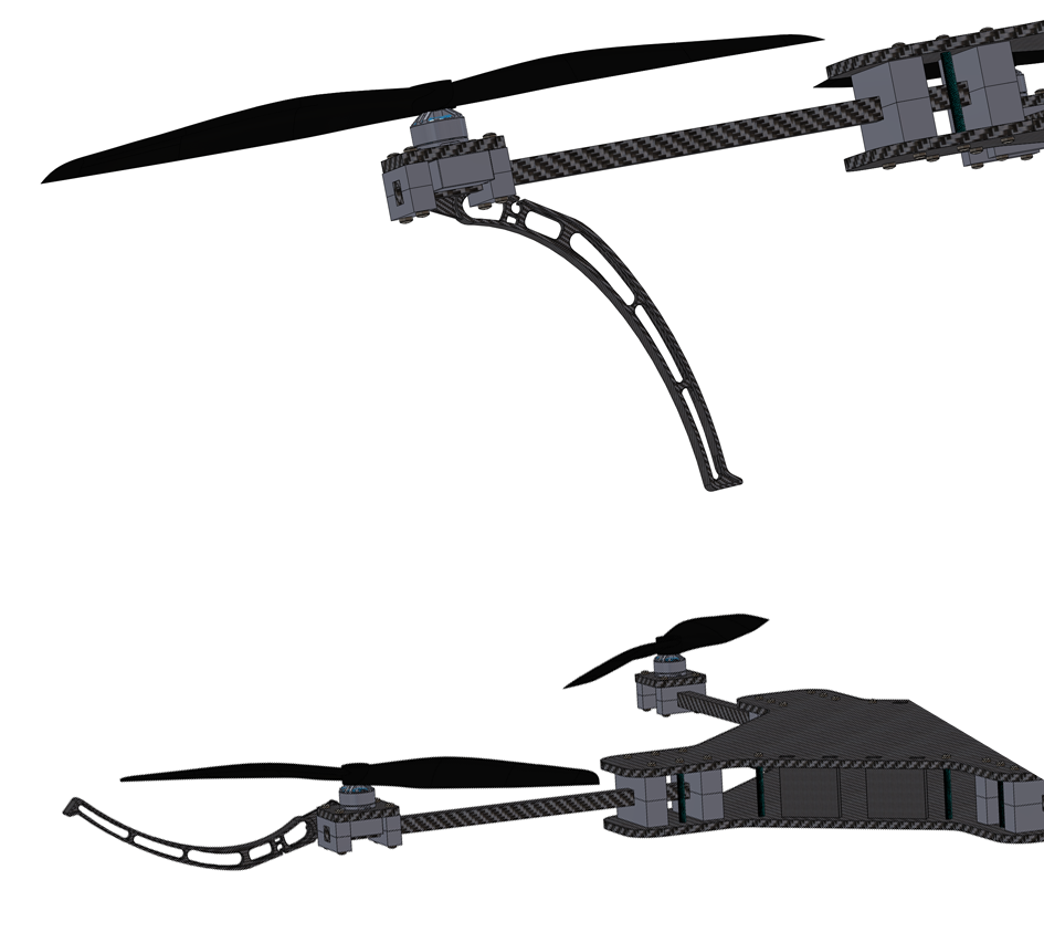
This week’s focus for our mechanical engineers has been the drone landing gear, as this is something that helps the drone land and protects the propellers from crashing into walls and whatnot. Our first attempt was to use a few servo-motors and we tried to implement them into motoring the landing gear as a simple folding solution. The servo-motors would be mounted under each propeller, so that each “arm” would have its own guard around the propeller.
After a few attempts, we could not find a proper way to mount the servo-motor to the propeller-arm. The brackets for the servo would either be too difficult to make or it would not be able to handle the stress from landing without breaking. We also found it difficult to come up with a design that would serve the purpose we wanted, as well as look good too.
Because of all the obstacles we stumbled upon with our initial idea, we decided to go for another idea with the landing gear. Instead of making a system that serves both as landing gear and propeller guards, we will make a system for landing only. We are planning to use servo-motors for this idea as well. However we will use it to fold the landing gear up under the body of the drone during flight time and fold it back down when we land the drone, just like the wheels on an airplane.
This operation can be controlled from the Control Center by the operator, along with a manual switch on the drone controller. Below are pictures of the old landing feet, which we decided to scrap due to multiple predicaments. We will make a new model next week to illustrate our new landing feet solution, as this is a part of our next sprint.
This week has been very productive in terms of developing subsystems and troubleshooting some of our initial ideas. We have re-designed some of our mechanical work and we have improved our software architecture, after recognizing the compatibility issues with ROS and the image transport issues we experienced. We are planning to lasercut a new prototype next week, perhaps in carbon fiber, to demonstrate the actual drone body, along with the ability to measure actual body weight for further calculations and analysis. This is something we are very excited about and we are looking forward to the next sprint session.