Date: 05.09.2019 – 12.09.2019
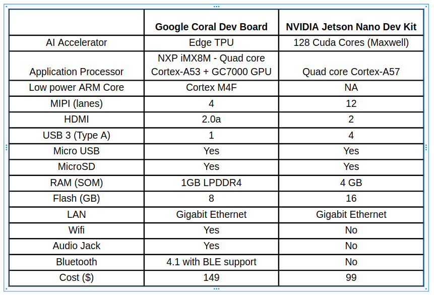
This week contained a lot of technical research and work that needed to be done in order to progress with the drone development. Last week we discussed which single-board computer we would depend on for the machine learning and after a lot of comparisons, we finally decided to use an Nvidia Jetson Nano for this project. The fact that the Jetson Nano has a GPU is very important to us, as it has 4 GB RAM while the Google Coral USB accelerator only has 1 GB RAM. The only thing that the Jetson Nano lacks is wireless connectivity, as it does not have WiFi or Bluetooth. To solve this matter we are planning to use a WiFi-adapter to establish a communication line between the drone and the control center.
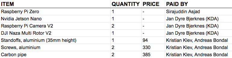
Since we are working with a somewhat limited economic budget, we talked to Jan Dyre Bjerknes from Kongsberg Defence & Aerospace about loaning some components for our project. Jan Dyre is also project leader at LocalHawk, which is an annual summer project in Kongsberg, and is known for working with unmanned aerial systems. He was willing to supply us with some high quality drone components, along with an Nvidia Jetson Nano, so we did not have to purchase these components with our own budget. Some of the hardware components we are working with right now are:
- Single-board computer: Nvidia Jetson Nano
- Backup single-board computer: Raspberry Pi Zero
- Flight controller: DJI Naza Multi Rotor V2
- Motors: 4x DJI E800 3510
- Camera: Raspberry Pi Camera v2
Our mechanical engineers have ordered a few parts as well, such as screws and standoffs for the drone chassis, along with carbon fiber piping to mount the motors. In order to inspect the drone body properly and to preview its design in reality, we made a prototype using a laser cutter. We used plywood material since it’s cheap and easy customizable.
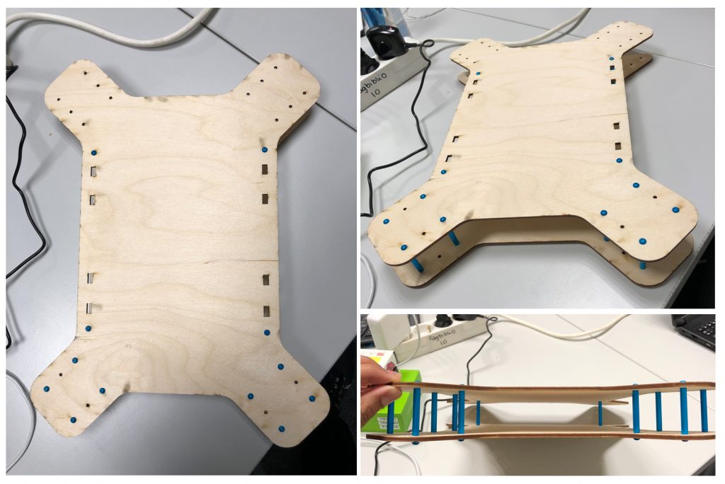
After making a prototype, we realized that we might encounter some problems trying to stabilize the drone, simply because the body was not symmetric. If one side of the drone (width) is larger or smaller than the other side (length), we need to calculate and adjust some parameters in the flight controller to maintain a stable flight time and to roll and pitch properly without losing balance. These parameters needs to be calculated for each motor, so instead of spending a lot of time calibrating this, we decided to change the body size of the drone instead to make it symmetric.
We also encountered another issue with the stabilization of the drone, and we were informed that we should use squared pipes/arms to mount the propellers and motors, instead of using round pipes. The reason why this is preferable is because the motors must be straight-balanced to avoid unstable flight time, and it is much easier to straighten a squared pipe than a round pipe, simply because you can see that the arms and motors are straight-balanced.
We spent some time planning the system architecture as well, in order to see the full picture of how our subsystems communicate with each other. These subsystems are decided upon the system requirements and will most likely change little by little as time goes by. We have both on-board and off-board systems, which means that we have subsystems located on the same platform as the drone, and we have some off-board subsystems located on a remote computer or elsewhere. The system architecture portrays how these subsystems are linked to each other and how they communicate.
We have decided to use ROS, or Robotic Operating System, in order to communicate between the various components in our system. As a quick introduction, it is a robotics framework where one builds a network of nodes: each node can send and receive messages on what’s called a topic. A topic is simply a name that separates messages from each other. For instance, a camera could send a message on the topic “/imageTaken”, which alerts the rest of a system that it took a picture, and the message itself could contain the image data. ROS communicates over TCP, which means that we can create a distributed network of nodes running on different machines as long as they are connected to the same network. We will be using WiFi to communicate between the drone and the control center.
It is good practice for each node to only drive a particular part of the system: for instance, one should have a node which drives a sensor and passes the information along to a motor node, rather than one node that listens for sensor input and then moves the motor directly. This makes the system more robust and more flexible, if one for instance wants the motor to be driven from a secondary source as well. The communication is easily handled by using ROS, meaning that programming this becomes a trivial task. This philosophy will be applied to our project as well.
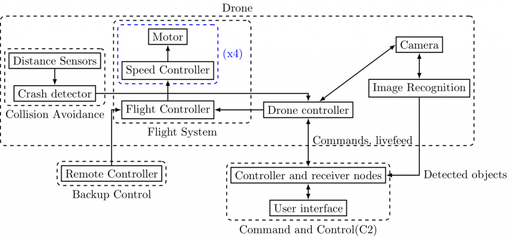
The diagram represents the first iteration of our overall system architecture. As one can see, it is built up of three main elements: Command and Control (C2), the drone itself and the remote control. The drone will be controlled mainly from the remote controller, but we hope to be able to control it from C2 as the project goes on.
The control station C2 will consist of a graphical user interface, which will be its own ROS node, and which will send and receive commands to smaller nodes. These smaller nodes will deal with sending the actual commands to the drone controller, and translate them from a request into a workable action. They will also receive sensory data from our drone, primarily a live feed from the camera, as well as the image recognition data.
Moving up to the drone, the main component will be the drone controller. It is likely to become its own little cluster of nodes, running the camera as well as the image recognition, with nodes that transfer the feed from both to C2. This cluster will hopefully be able to run off of a single Jetson Nano card from NVIDIA, but we have a backup plan if it’s too much for it to handle.
There is also the collision avoidance system, which would consist of distance sensor pointing in every direction out from the drone, and which would be able to detect walls. If the drone were to fly too close to a wall, the collision avoidance system would be able to take control and steer us clear. This is not a high priority goal for the project however, because that is a significantly harder task than originally assumed.
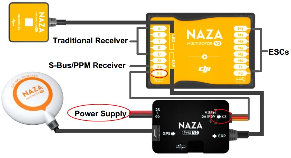
Other than that, there’s a drone flight controller, which is going to be an off-the-shelf part. It will be connected to four speed controllers, which again are connected to a motor each. It contains all the instruments it needs to fly and keep itself stable. The flight controller we are planning to use is produced by DJI and is named Naza Multi Rotor V2. It is packed with a lot of features and it gives us tremendous possibilities to expand the functionality of our drone. It is well-documented and easy to use as well.
We have been documenting our financial expenses in our technical budget, since we are required to purchase some parts and components for the drone. The list is not complete yet and there are still some components that we need to purchase. We are doing our best to keep the expenses as reasonable as possible, and we are trying to loan the expensive components that we need instead of buying brand new ones.
We have done a lot of work this week and we are very satisfied with the progress so far. We have started setting up ROS on the Jetson Nano and hopefully have this up and running in a couple of days. We discovered some things that needs to be improved with our prototype, which means that we need to re-design the 3D model as well. This is something we will focus on during the next sprint, along with some ground software implementation to get things running.