The frame as it was shown, is printed with the Ultimaker at school (Figure 1).
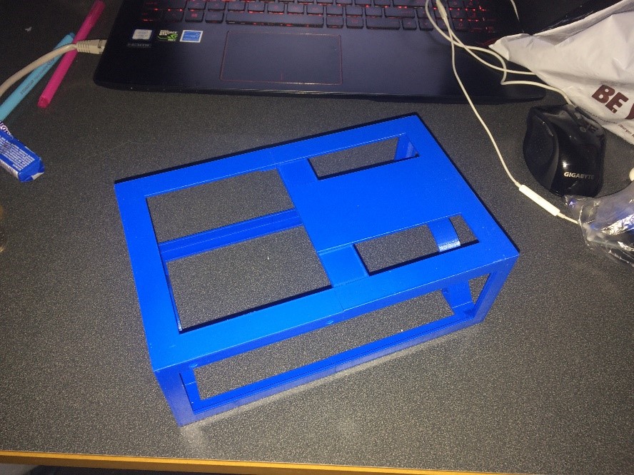
Figure 1 First prototype 3D printed frame
The outer dimensions of the frame were almost good. The following dimensions are changed (Figure 2):
- The arm supports were both too tight, so these are made wider
- The frame was too small so the width of the frame is increased by 25 mm
- The frame was too low, so the height of the frame is increased by 10 mm
- To make the frame more stiff, there are made extra ribs
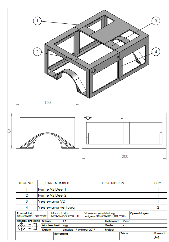
Figure 2 2D-drawing of the assembly of the frame
In according to these dimensions, it turned out that it would not be possible to put both servomotors inside the frame. Since the frame had the right dimensions in according to the arm, another system was required. We found out that it is possible to put the servomotors (1) outside the frame and use bolts and threads (2). Figure 3 shows the system for the 2-coordinate system.
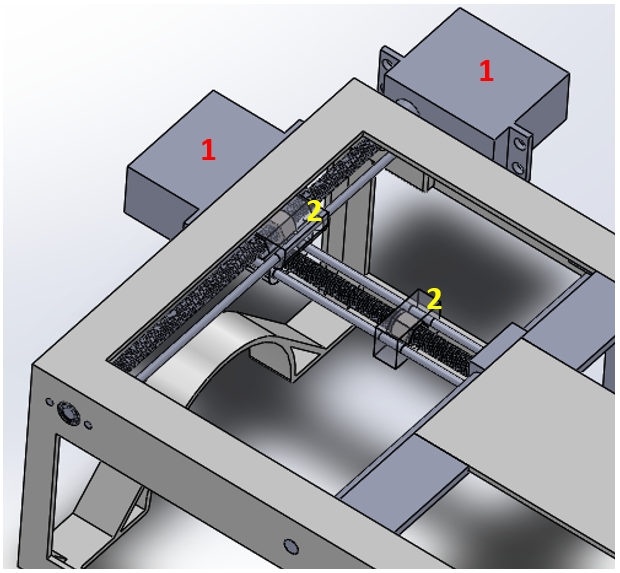
Figure 3 The new 2-coordinate system
To make the pen move, there is another mechanical part required. For this movement system a 180° servomotor is used. The parts which connect the servomotor to the pen will be printed and assembled with bolts and nuts. Figure 4 and 5 show the system of the pen movement.
Figure 4 Mechanical part pen
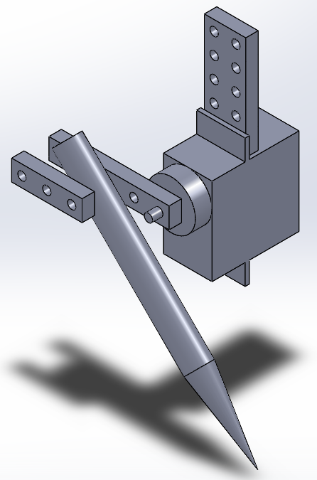
Figure 5 Pen movement in system
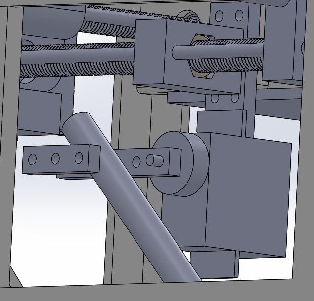
The adjusted and additional parts are printed. Some parts needed to be adjust, because the holes were not big enough. The holes in the leading parts for the 2 coordinate system turned out smaller than supposed, causing fraction. The parts which are holding the pen were also smaller than supposed, so the holes in the parts had to be reamed. To lead the parts, thin copper axils are used. We use this material because it is very lightweight and strong enough to lead. Now that all the parts and materials are collected, we can start with saw the right dimensions of the thread and axils. After this the 2 coordinate system is assembled (figure 6). Also the mechanical part of the pen is assembled (figure 7).
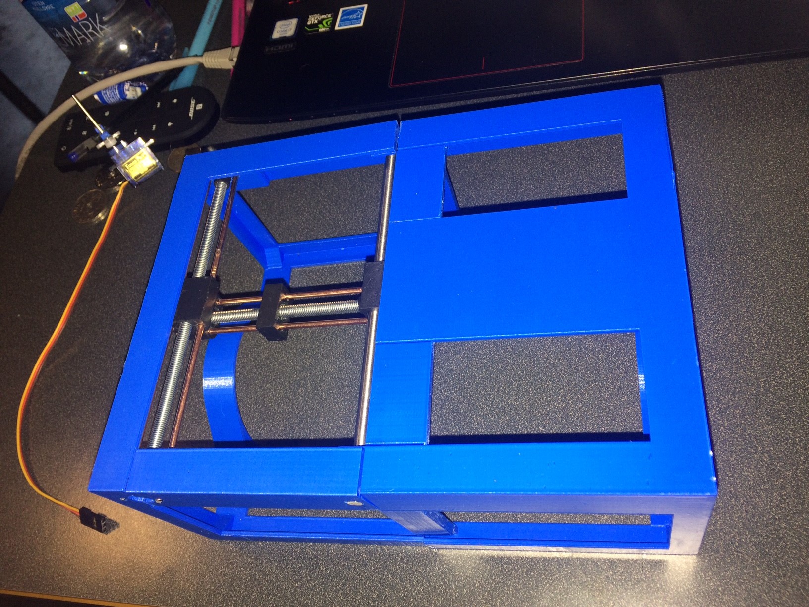
Figure 6 Assembly 2-coordinate system
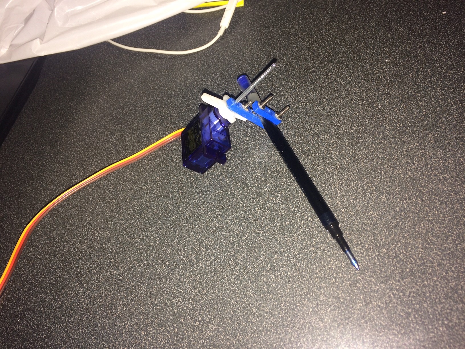
Figure 7 Assembly pen movement
While assembly the product, there were some complications. Three printed parts have to print again before the entire 2 coordinate system can be assembled.
All the parts are printed in the right way, so the system can be assembled again. Figure 8 shows the result of the assembled system.
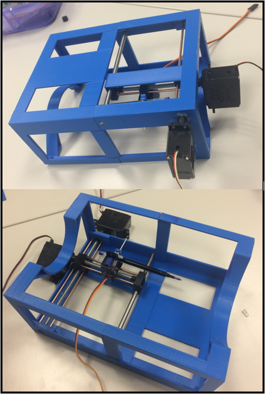
Figure 8 Result of the assembled system
The video in the following link shows the working 2 coordinate system.
https://www.youtube.com/watch?v=P2ci6r5Zgbc
To connect the servomotor for the pen to the moving part in the middle, we had to adjust the servomotor. We had to polish the motor and move the wires to another place. Figure 9 shows the adjusted servomotor.
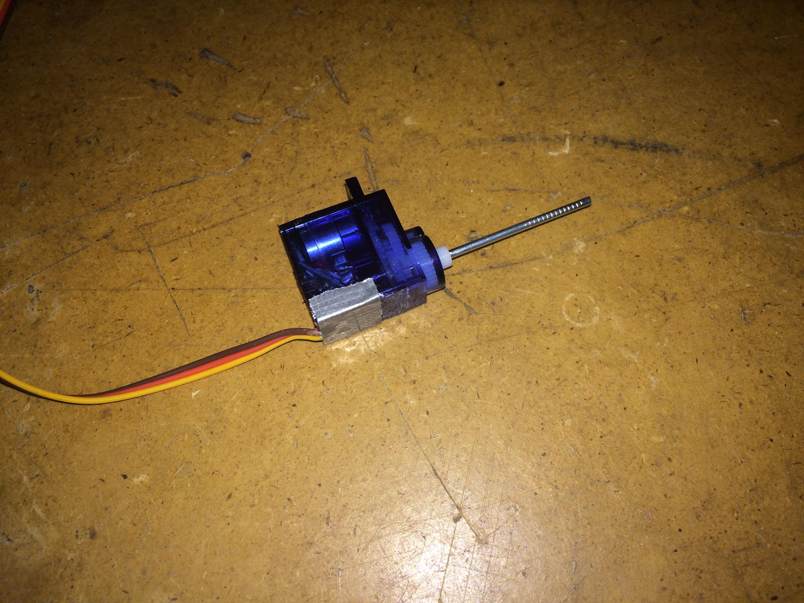
Figure 9 Adjusted servomotor
To connect the spindle, roll bearing and servomotor, we decided to print several parts. Figure 10 shows how these parts are assembled in a 3D-model and figure 11 shows an exploded view in a 2D drawing. Part 2 and 4, part 4 and 5 and part 3 and 6 (rollbearing and frame) are connected with glue. The servomotor and part 2 are squeezed together. In according to some tests it turned out it is strong enough when it is squeezed together. We chose this way to connect, because we cannot add glue to the servomotor, since it is a prototype and the servomotors will be used for other purposes.
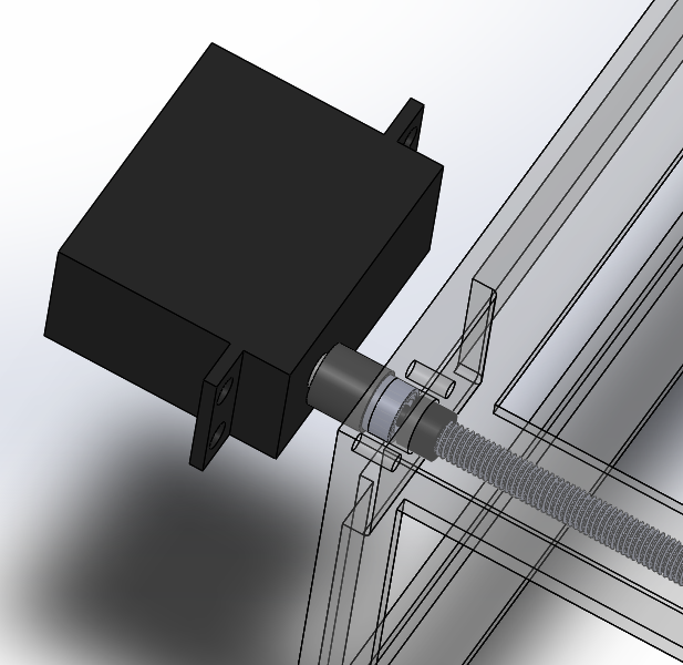
Figure 10 3D-model of the connection between servomotor, roll bearing and thread
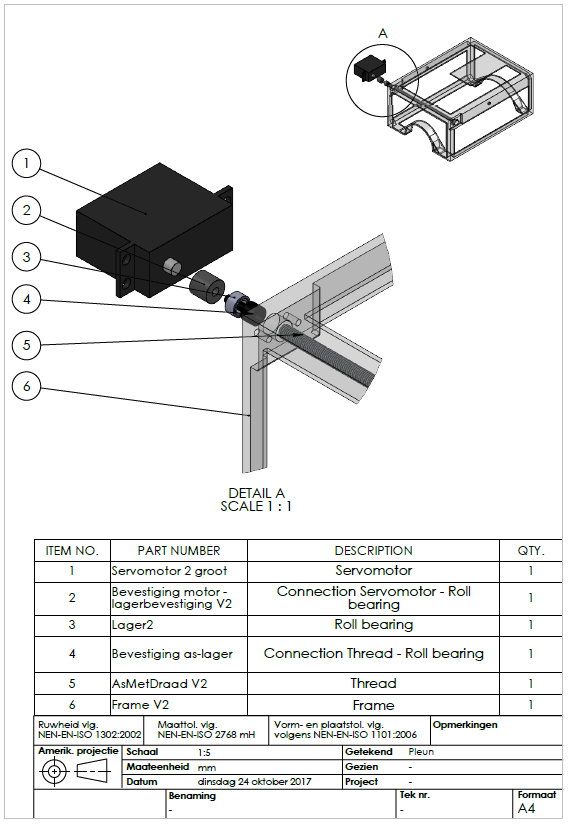
Figure 11 2D-drawing with an exploded view of the connection between servomotor, roll bearing and thread
Now the servomotors are only connected by the small pin. To make the servomotor connect more stable, we decided to print simple parts. We use these parts and double-sided tape so we can disassemble the motors after. Figure 12 shows a 3D-model of the connections and figure 13 shows a picture of the result.
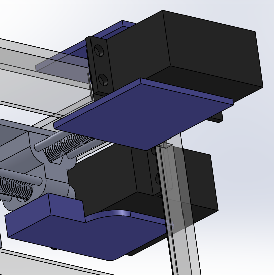
Figure 12 Connection between servomotors and frame
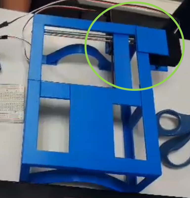
Figure 13 Result of connection between servomotors and frame
After testing the servomotors, we concluded that this way of connection is good acceptable for the product.
The camera, LEDs and raspberry pi have to be connected to the frame. We decided to put the Raspberry Pi on top of the frame. According to this way, we have enough space to connect the wires. Figure 14 shows a 3D-model of the Raspberry Pi on the frame.
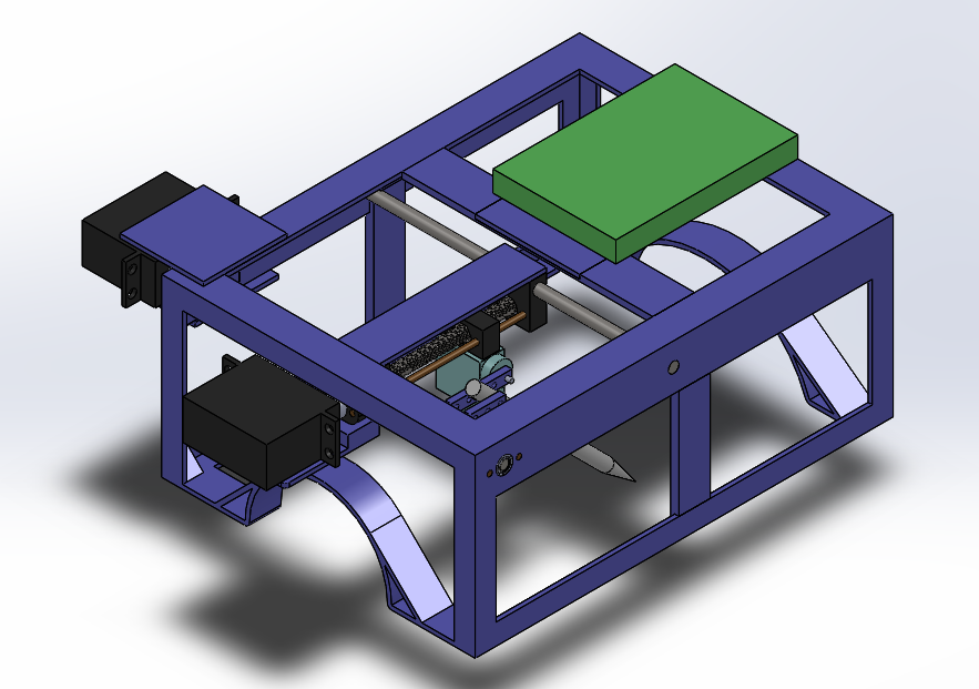
Figure 14 Raspberry Pi on top of the frame
The camera has to be connected underneath the frame (under the Raspberry Pi). Since we wnt to use the camera after this project, we cannot connect the camera with glue to the frame. We decided to print a part with holes in it which we can connect to the frame with double-sided tape. Figure 15 shows a 3D-model of the printed part and figure 16 shows a picture of the camera connected to the printed part.
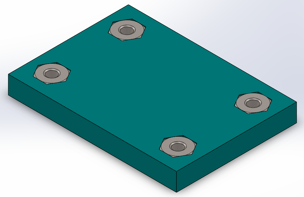
Figure 15 3D-model of the printed part with nuts
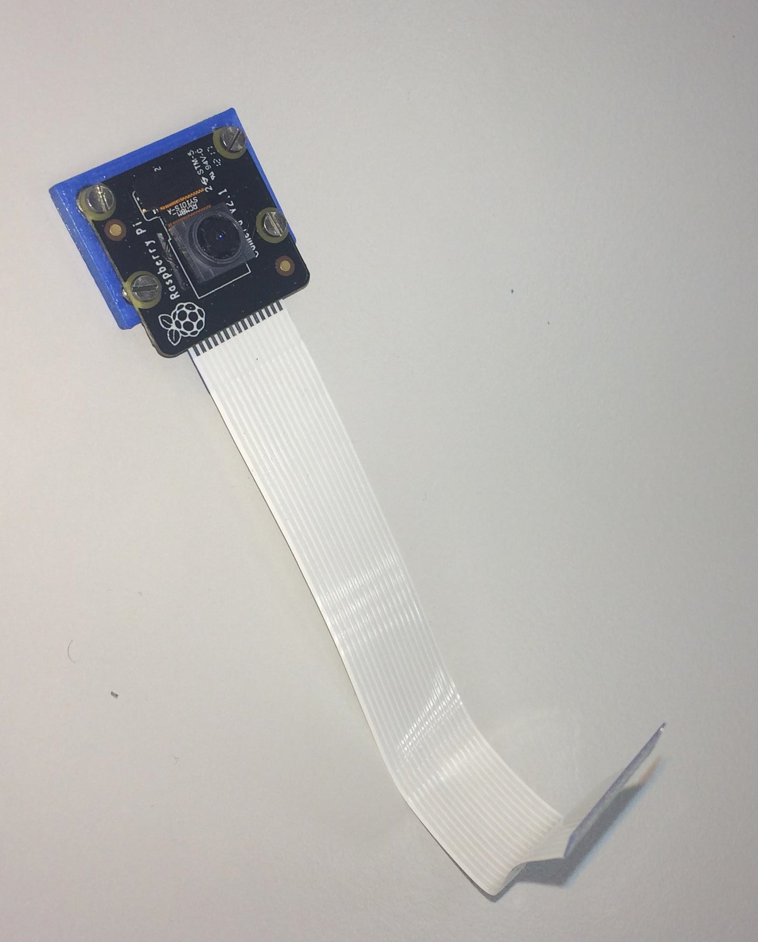
Figure 16 Result of connection between camera and printed part
To make the camera work properly, we use 4 LEDs besides the camera. To connect the LEDs we decided to print another part. Figure 17 shows a 3D-model of the printed part together with the part for the camera.
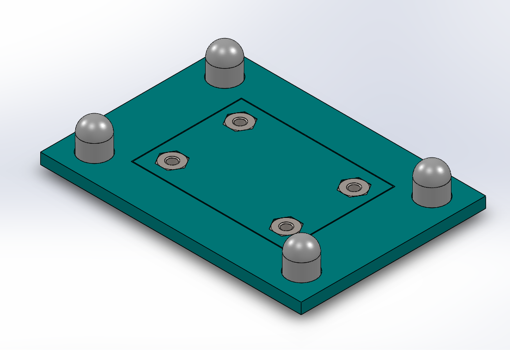
Figure 17 Printed parts to connect camera and LEDs
The other part is printed and connected to the part with nuts, together with the LEDs. Figure 18 shows the result of the assembly.
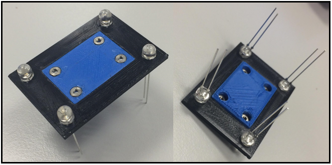
Figure 18 Result of assembly camera and LEDs
To connect the device to the arm, we dicided to use Velcro. This is the easiest way to connect the device. Figure 19 shows the result of the device connected to the arm with Velcro.
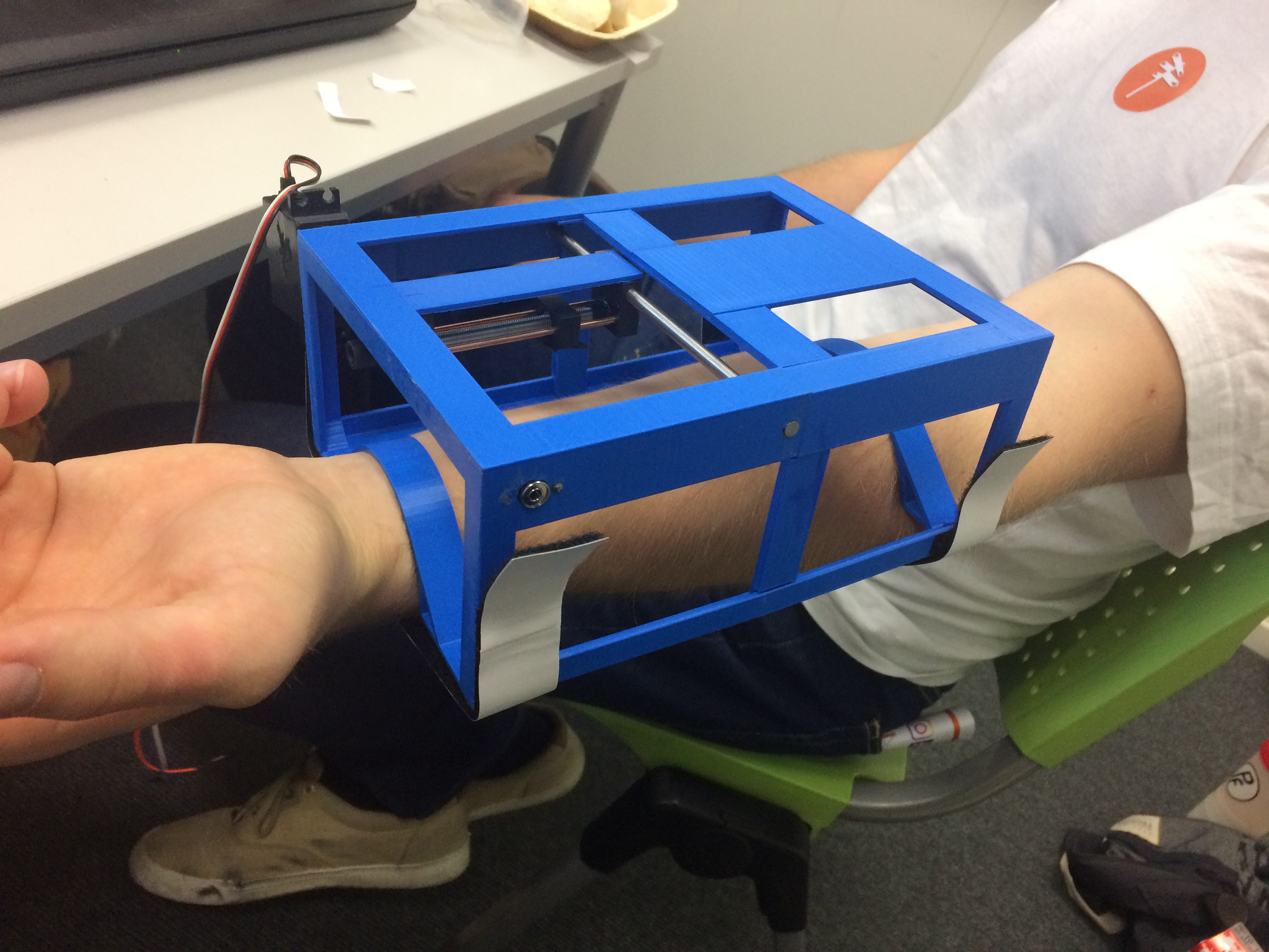
Figure 19 device connected to the arm
We deciced that we are using another camera (IR camera), so we had to adjust a little bit to the frame. We are not using both the parts shown on figure 18 anymore, but only the black part. The new camera we are going to use is bigger than the other one, so it has to be connected on top of the frame in stead of underneath. According to this, we have to make a small hole in the frame for the camera. Figure 20 shows a 3D-model of the new method and figure 21 shows the result of the part connected to the frame. We are going to use souble sided tape to connect this part,
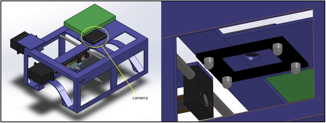
Figure 20 3D-model of the new method according to the camera
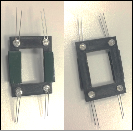
Figure 21 Result of the part to connect LEDs to the frame with double sided tape
The hole for the camera is drilled in the frame. While we were testing the device, it turned out that it is better to have more light to expose the arm. This is why we drilled more small holes in the frame, which makes us able to add more LEDs to the frame. Figure 22 and 23 shows the results of the drilled holes in the frame.
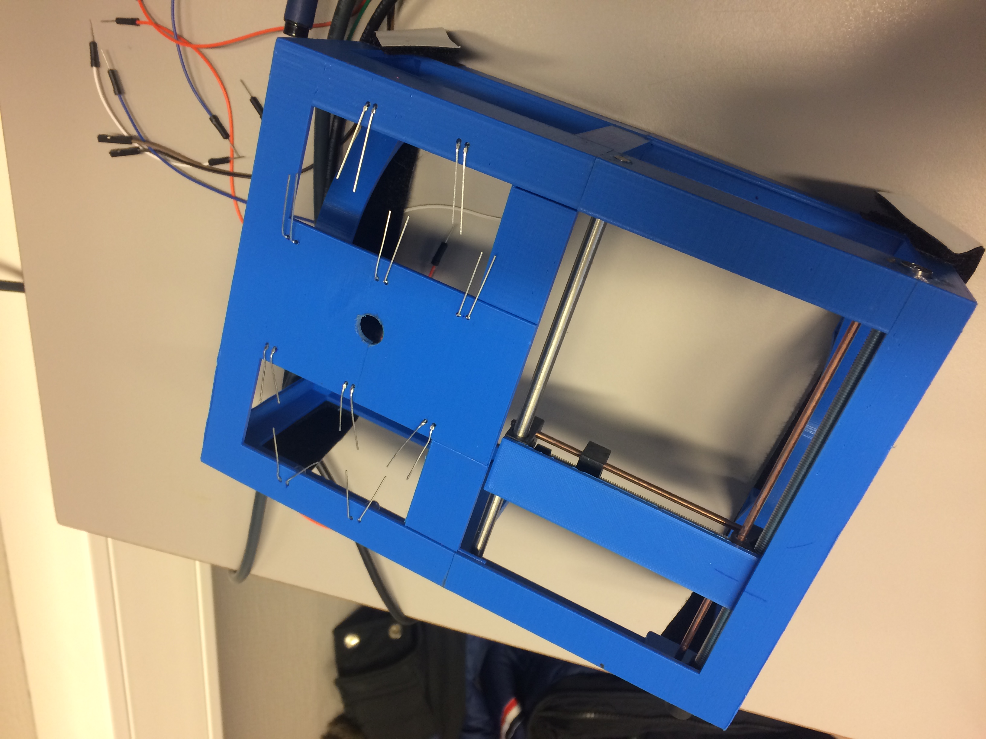
Figure 22 Result of the drilled holes in the frame
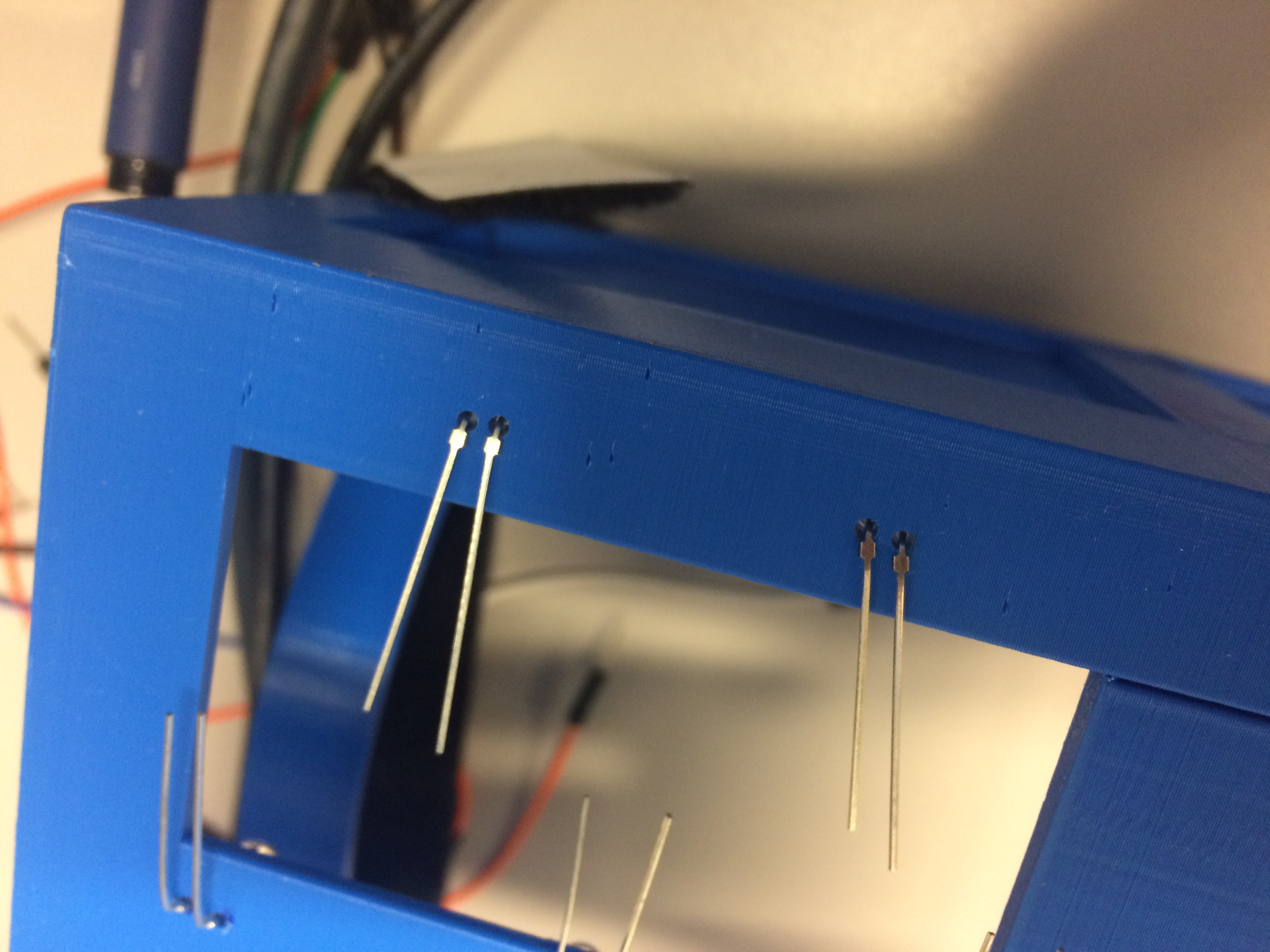
Figure 23 Result of the small holes in the frame for the LEDs
After testing, it turned out that the part to connect LEDs to frame with LEDs is not necessary anymore. Figure 24 shows a picture of the result without the connecting part.
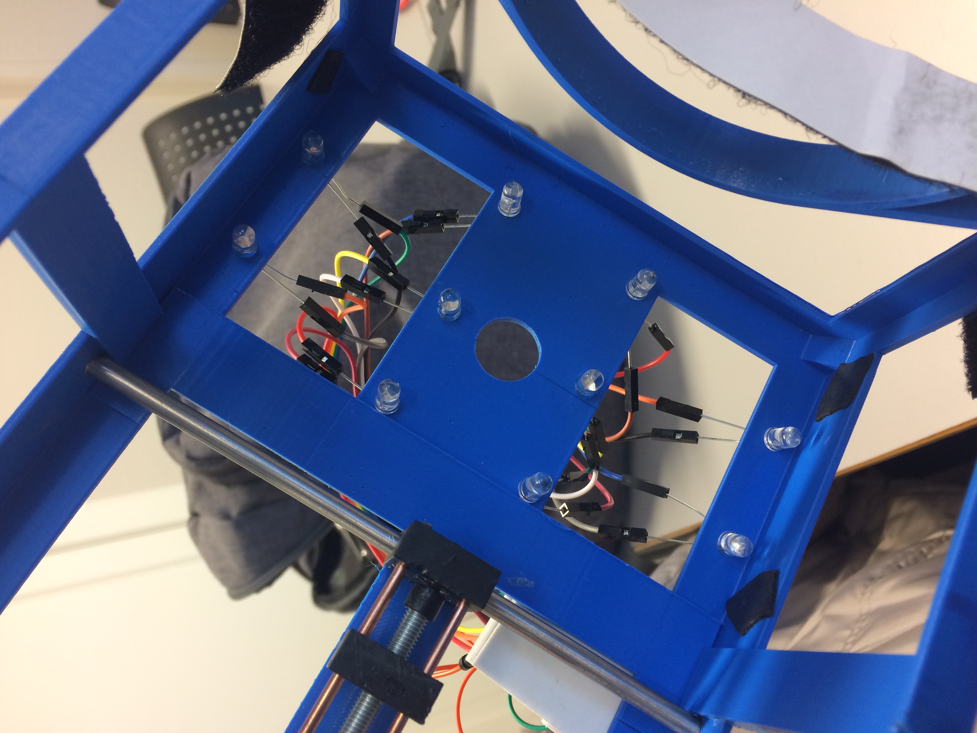
Figure 24 Frame with extra LEDs and without connecting part
Following are the assembly drawings and all 2D drawings of the individual parts:
1. Assembly drawing robot needle
1.1 Main frame
1.3 Flat servo holder
1.4 Part reinforcement system
1.5 Connection motor – axle
1.6 Servo holder
1.10 Reinforcement top
1.12 Reinforcement sides
1.13 Leading part thread small
1.17 Leading part thread big
1.18 Leading part axle
2. Assemblydrawing pen
2.1 Connection pen short
2.2 Connection pen long
3. Assembly drawing connection thread – roll bearing – servo motor
3.1 Connection axle – rollbearing
Following document explains how the robotneedle is produced, step by step:
The production of the robotneedle, step by step