Figure 1:
We have started to draw a sketch of the frame in SolidWorks. The length of the arm is approximately 20 cm. We used this dimension for the length of the frame.
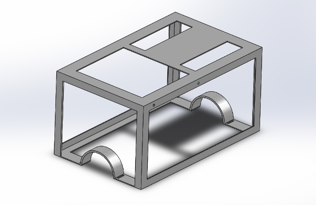
Figure 1
Figure 2:
According to the weight, we want to make the frame as light as possible. First, we wanted to use a 1 mm thickness, but the frame will not be strong enough when you print it. We adjust the thickness to 2 mm. To make the frame more solid, we used an extra reinforcement in every corner and extra ribs for the straps.
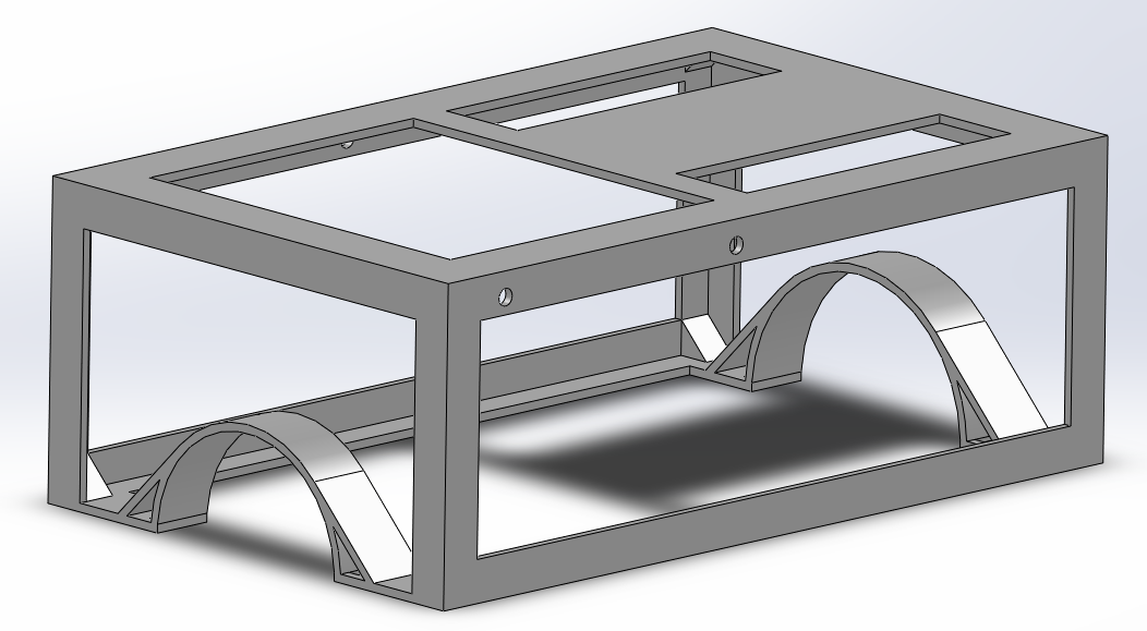
Figure 2
Figure 3:
For making it possible to print the frame with the Ultimaker, we had to devide the frame in three parts.
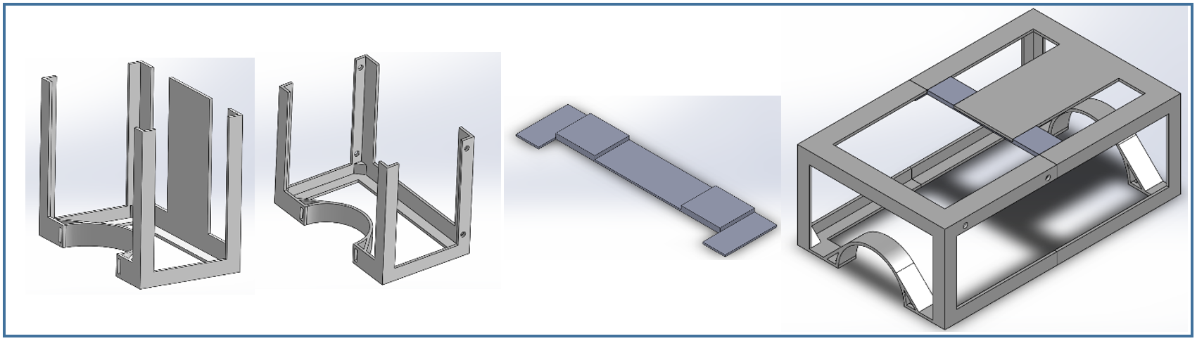
Figure 3
Figure 4 (the gears and roll bearings are not drawn yet):
To make the 2 coordinate system, we are going to use gears connected to stepmotors (1). On the other side (2) we are going to use an axis with a roll bearing and a gear, to guide the system.
Following are the reasons why we’re using this system:
- The components are small and light (required).
- The device and components are too small for a chain drive/ belt drive.
- It is an easy and cheap way to drive the system.
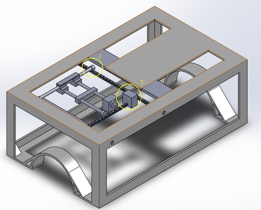
Figure 4
This link shows a simple video of the coordinate system:
https://www.youtube.com/watch?v=ITnPJ9eS61g
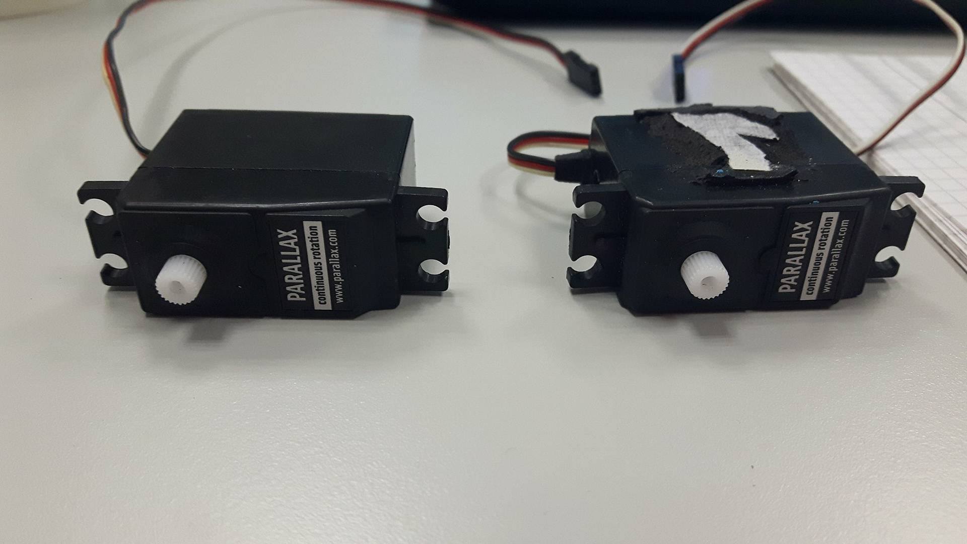
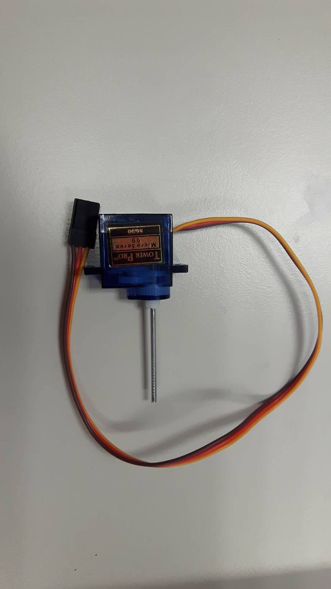
Chose to use servomotor instead of stepper.
Needs 3 servomotors:
1 to x axis (rotate 360 degrees)
1 to y axis (rotate 360 degrees)
1 to angle (rotate max 180 degrees)