Hei
Vi er gruppe 4 bestående av 5 medlemmer spredt utover ingeniørstudiene på HSN.
Fernando Almeida (maskiningeniør student)
Susanne Larsen (dataingeniør student)
Brynjar Thorri Jonsson ( dataingeniør student)
Ole Halvor Ingolfsrud (elektroingeniør student)
Tuan Anh Trinh (elektroingeniør student)
Oppgaver.
Vi skal lage en kaffemaskin med en tilhørende termos, hvor begge av produktene skal ha praktiske egenskaper som F.eks varmeregulering, termostat, mengdemåler og et høyt justerbart utvalg av drikke. I tilleg skal vi ha med en app som skal kommuniserer med kaffemaskin og via appen skal vi også kunne velge hvilken drikker vi vil ha.
Framdriftplan
(22.08.17)
Den første uken brukte vi for det meste til å drøfte ideer og få bekreftet at ideene våre var brukbare oppgaver. Etter å ha bestemt oss for kaffemaskin-ideen, diskuterte vi mer om oppgaven og prøvde å legge til flere elementer til oppgaven.
(29.08.17)
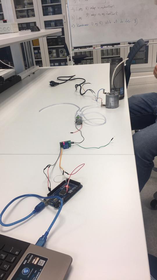
Den andre uken fant vi 2 ulike kaffemaskiner som vi demonterte for å finne mulige deler. I den ene kaffemaskinen fant vi ett varmeelement vi har tenkt til å bruke videre. Vi koblet en spylervæskepumpe sammen med varmeelementet og styrte pumpen med en arduino. Varmelementet måtte vi styre manuelt, siden vi på den tiden ikke hadde ett rele som passet.
(05.09.17)
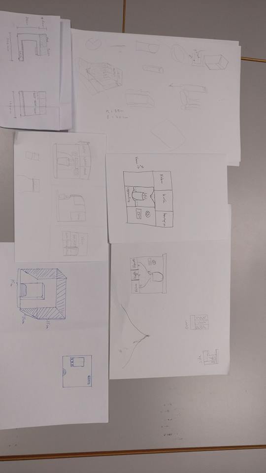
I tredje uken snakket vi mye om design og hvordan vi vil at operasjonene i kaffemaskinen skal fungere. Vi laget illustrasjoner av hvordan kaffemaskinen skulle se ut, og fant ut at alle hadde en ganske lik tanke om hvordan sluttproduktet skulle se ut. Vi har også begynt å se på en app som skal høre til kaffemaskinen, og noen komponenttegninger.
(12.09.17)
I fjerde uken satt vi å testet ut forskjellig komponenter som vi skal ha videre i prosjektet som varmeelement og vannpumpe. Der brukter vi rele til hvert av komponent som blir styrt via Arduino. Siden utgangspenning fra usb til pcen ikke takler drift av vannpumpe valgte vi å koble opp en ekstra 9V batteri. Og varmeelemet bruker vanlig AC spenning så var det bare koble den via et rele og rett inn i stikk kontakt. Vi fikk til å varme opp vannet men ikke til temperatur som vi hadde ønsket, siden varme element hadde temperatur måle fra før valgte vi å bruker den til å overvåke temperaturen i varmeelement.
(19.09.17)
I den femte uken satt vi sammen å se over designe til selve dispenser som Fernando har laget via SoliWorks. Vi har også tatt med en mobil lader som vi skal modifiserer sånn at vi har en stabil 5V DC spenning til diverse komponenter som vi skal bruke, siden 9V batteri som vi brukte til pumpemotor sist gang holdt i 10 min. Vi satt å diskuterte hvordan framsiden av kaffe vil ser ut og hvor mange knapper vi skal ha med.
Mechanical engineering work progress:
The group decided to work on a “smart” coffee machine and a “smart” coffee cup, that both combined can ease the daily life of coffee consumers.
The project includes two main assemblies, the thermos cup, and the machine itself.
The machine will be a stationary object with somewhat large dimensions. At this stage, we have only come to some rough dimensions just to get a feel of how big the machine needs to be, we came to the following dimensions: L:400mm W:300mm H:300mm.
Since we are only working on the machine at this stage, we have not yet made any predictions, apart from the maximal height, to how the cup will look and how it will actually function.
The first design phase was on the machines dispenser and the mechanism to pour coffee from the reservoir in to the cup.
The course supervisors informed us of the different alternatives we had to produce our parts, and our primarily design was based on that information.
We designed our first assembly in a way that it could be “easily” printed by the machines available at the school. The main requirement was that the parts to be printed should not exceed a 200mmx200mmx200mm dimension.
In the design, we used an average thickness of 3mm on all the walls of the machine and no single part was larger than 100mm in height, depth, or width. Despite the efforts to make the parts as thin and small as possible, and that all the parts were inside the required parameters for a printable part, we were not allowed to print them. The average printing time for some of the smaller parts was up to 19 hours of printing, and that was the calculated time if no errors or fails happened in the printing process. We had three equal assemblies to be printed, and that would bring us up to a printing work of several days which made us have to switch strategy and change the manufacturing process as well as the design.
We were advised to choose wood and the laser cutter to produce our parts.
While the assembly design remained the same, all of its constituents parts had to be redesigned, since using wood and the laser cutter requires using 2 dimensional drawings and a completely different assembly approach.
One of the challenges in the design is the fact that some of its parts are round. We want to have control over the level of powder inside our dispensers, and for that to happen we will have to build some of the parts in Plexy glass. The idea is to create a small, narrow window in the front of the dispenser, but since the part is relatively tall, and it will be cut in a way that it will allow it to bend, we will have to use 4mm plywood to ensure enough strength to the part, and 1mm Plexy glass for the window.
Another challenge is to get the dispenser system enough sealed so that the coffee or tea powder won’t get inside the engine and sprockets compartment. Using wood will make it hard to get the mechanism completely sealed, and the use of other materials will have to be considered.
To assemble the parts together we will use a type of super glue that is specifically specified for porous materials.
(10.10.17)
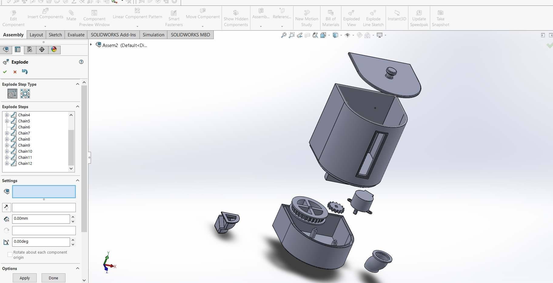
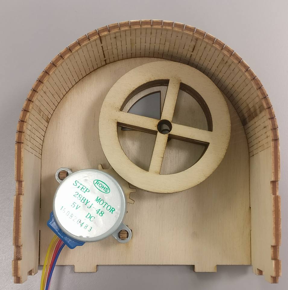
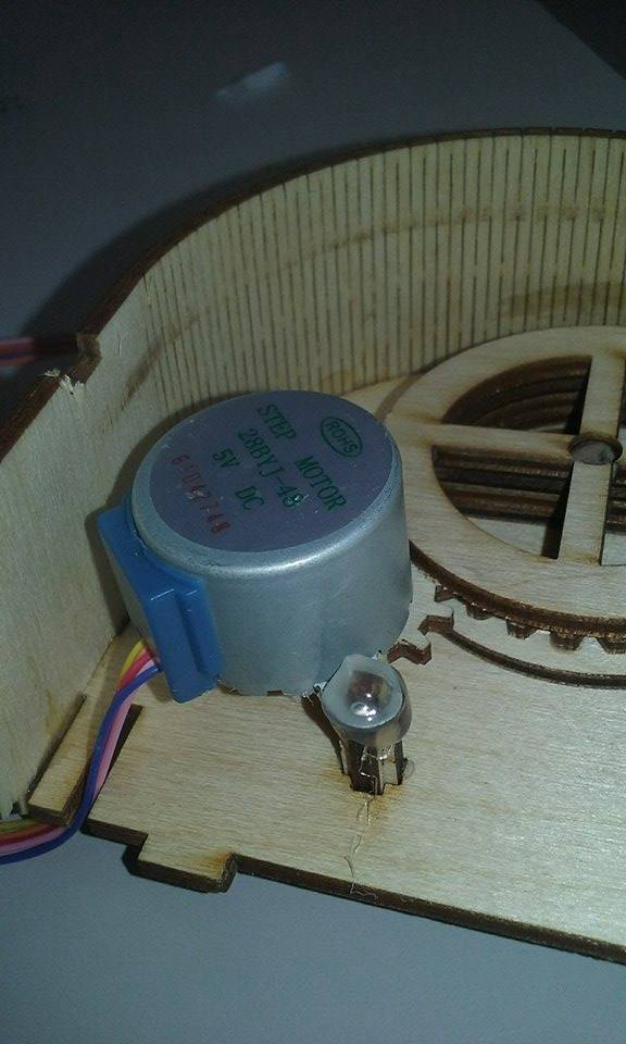
Denne uken har vi klart å få fram den første prototypen av en av våres dispenser. Sånn dere kan se på bilde under har vi valg å gå for tre material på grunn av det er den eneste material type som vi har tilgang til. Dispenser blir delt oppi to deler der toppen er beholder til kaffe eller andre påfylling vare. På under siden ligger det to roterende tannhjul der en av dem koblet til stepmotor sånn blir styrt av arduino, tannhjul som er koblet til stepmotor skal styre andre tannhjul som er til porsjon måler der hvert av rutene inni tannhjul har en volum like mye som halv teskje.
(31.10.2017)
Mechanical engineering work progress (2):
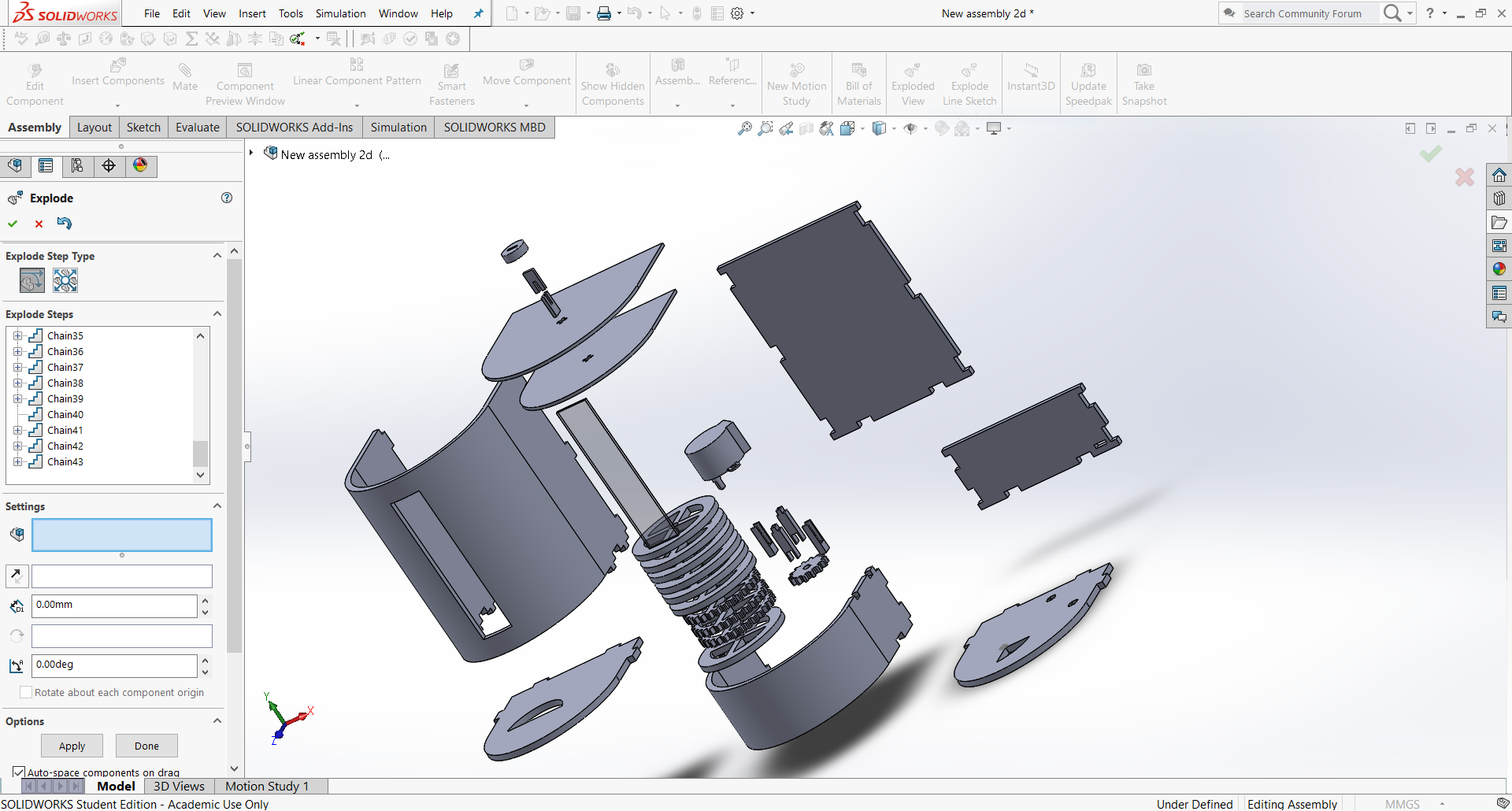
After cutting the individual parts of the dispensers and putting them together, we started planning how the main body of the machine would look like. We tried to combine ideas from the initial drawings made individually by all team members, and conceived a rough sketch of how the machine would look like.
We started at the top where the dispensers will sit.
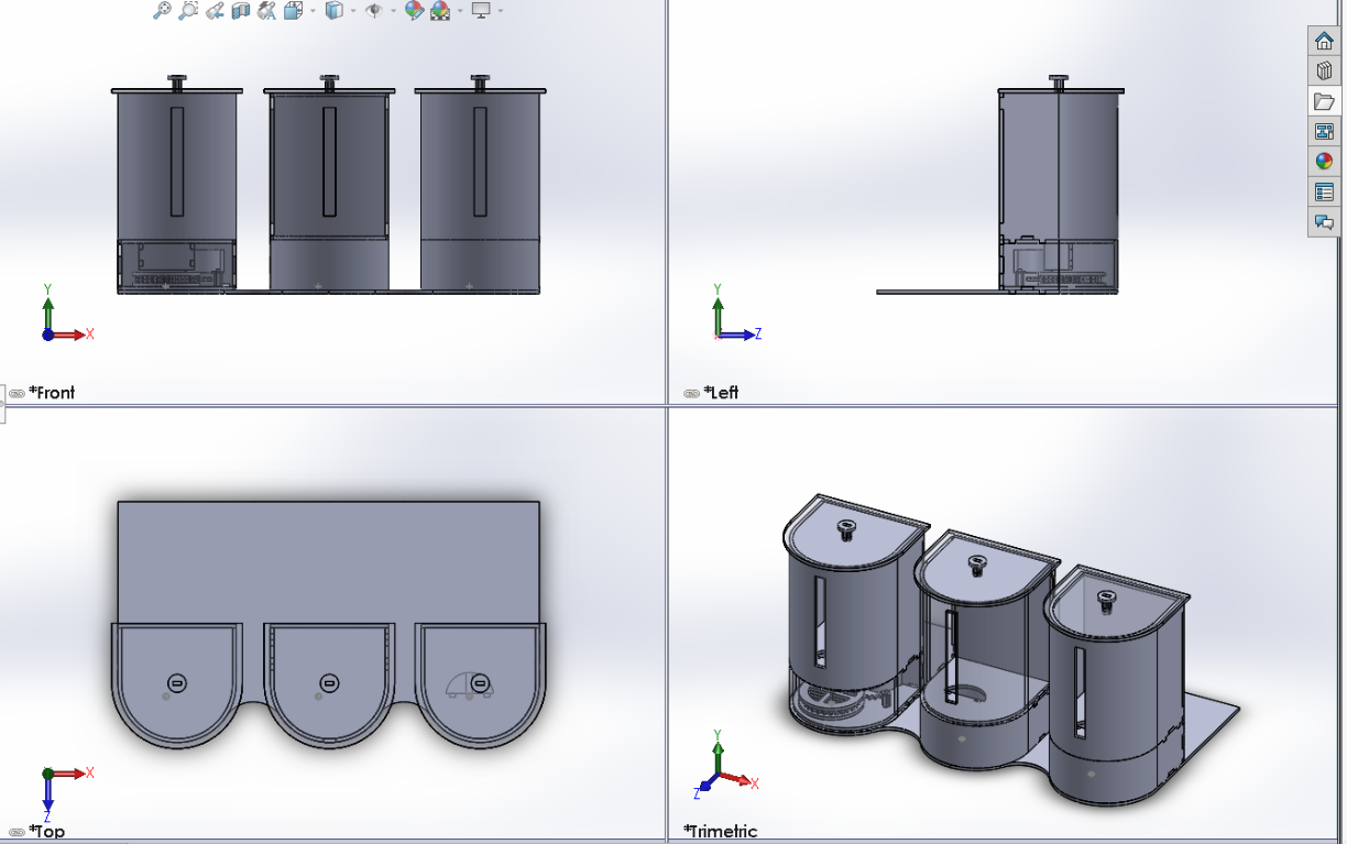
From there we went on by designing the rest of the machine, and made various small changes in the process. We are trying to avoid sharp corners as much as we can in the design. That is not the easiest task if we take in consideration the materials we are using.
One of the challenges encountered when drawing a 3-dimensional assembly that needs to be composed of “2D” (excluding thickness) elements are the round parts/edges, and to make it correctly so it fits properly. But not dealing with that would result in a square box with no special design.
The amount and size of all the electric components, and mechanisms that need to fit inside the machine is quite big, which resulted in a voluptuous machine. To make it more appealing design wise the dispensers suffered a considerable change in size, without affecting the main purpose of the machine and its intended functions. In mounting the parts together of the machine body, we had to use some pieces of 2×2 wood and screws which served as a kind of improved chassis and turned the structure sturdier.
We will continue to design now a grid for the bottom of the machine and a part that can help deliver the different powders to the cup as well as a solution for creating a water dispenser that doesn´t leak.
(07.11.2017)
Mechanical engineering work progress (3):
This week we accomplished the design and production of the smaller powder dispensers, the bottom grid of the machine and the part that will help deliver the powder to the cup.
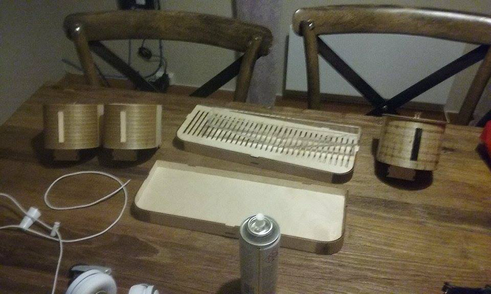
We also managed to assemble the mechanism of the 3 dispensers. To fasten the small step engines in wood pins was a bit of a challenge. We had to use an activator, and super glue. The engine exerts a relatively high torque (Considering its size and mount properties) on the mounts, to ensure a snugged fit we added hot glue at the connections.
As a rotation pin for the dispenser wheel, we used a ø 5mm steel rod and fixed it also with super glue.
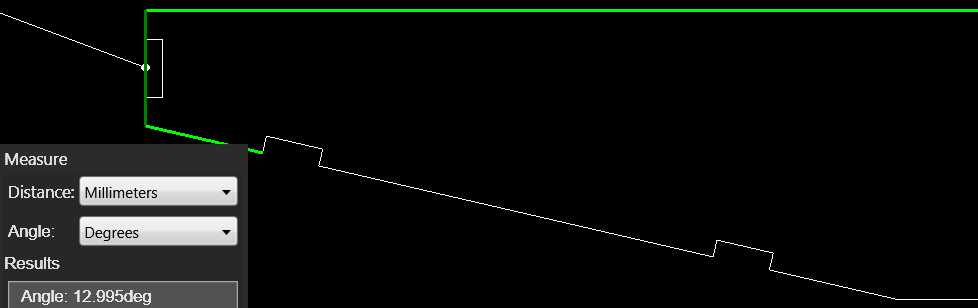
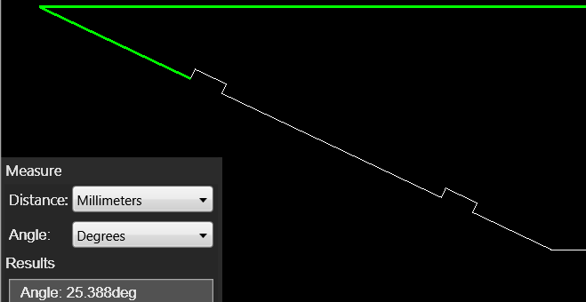
When we designed the part for powder distribution we didn´t knew how big the cup would be, so to make sure we had room, we used an angle of 13 degrees on the part, so we could end up with at least 16cm clearance.
After the part was cut and assembled, we ran a simple test by pouring coffee on it. The test showed us that the inclination on the part was not sufficient to overcome friction between the powder and the Plexiglas surface of the part. Since we now know that the cup is no bigger than 11cm, we can now redesign the part and increase the angle by 12 degrees.
(14.11.2017)
Mechanical engineering work progress (4):
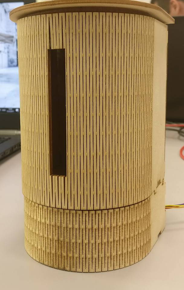
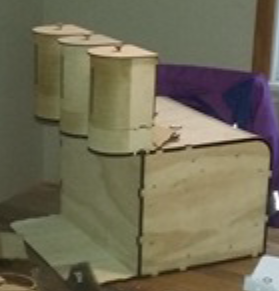
The machine is starting to get some shape now.
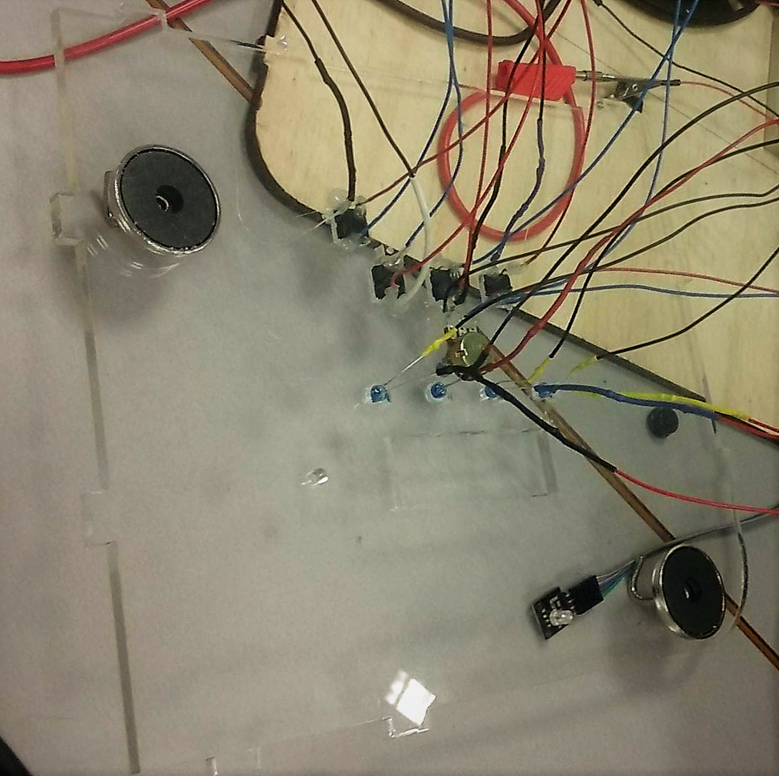
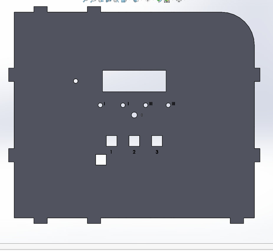
Almost all the electronic components are fitted inside and the question about the operating buttons came up.
We had initially agreed that we could just drill the holes as the assembly of the machine went, but since none of the buttons or lights we are using have frames to disguise the cuts, we optioned by drawing a new part with the holes on it. Since the part had to be cut anyway, the team thought it would be nice to be able to see through the machine, and we decided to make the side wall in Plexiglas.
We also agreed on having numeration on the different holes to indicate function.
(21.11.2017)
Mechanical Engineering work progress (5):
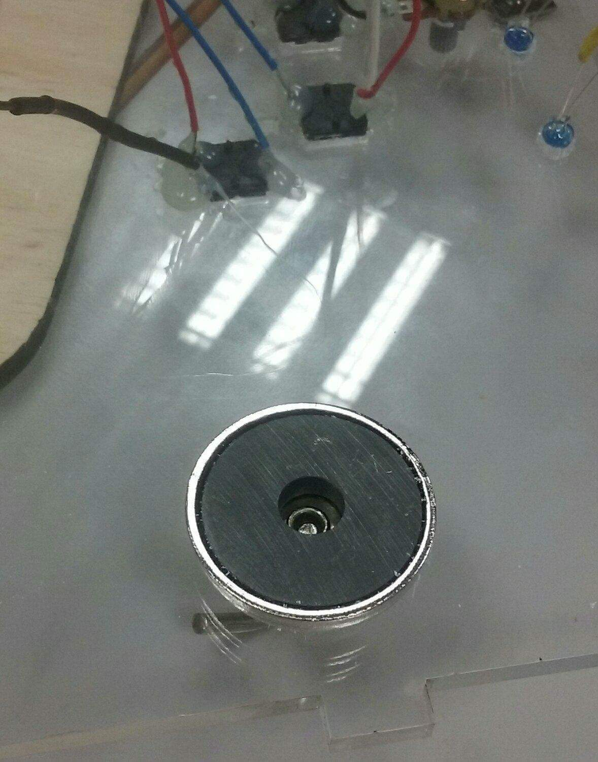
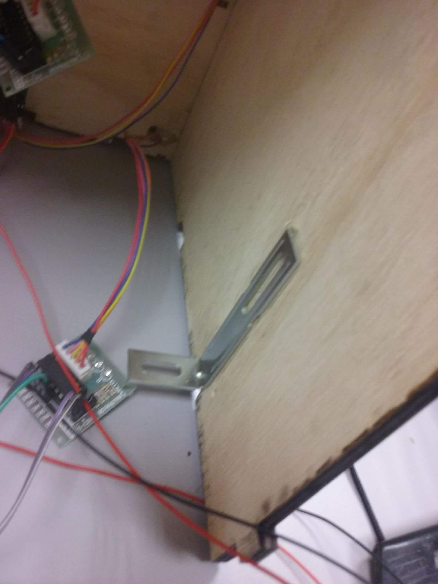
We have now cut the side wall in plexi-glass and fitted all the led lights and buttons on it.
Since this part is connected with several wires, we decided to set it in a way that could facilitate assembly and extraction. For that purpose, we added magnets on the corners of the part, and metal hooks on the interior of the machine.