Week 14:
Salim & Mohammed Ø:
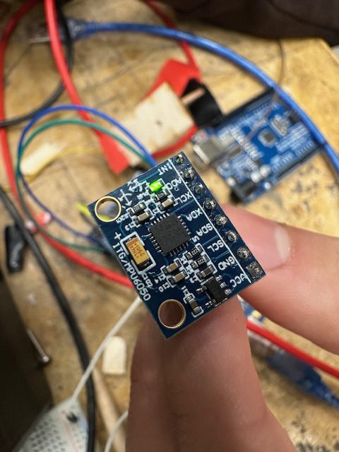
This week we got the MPU6050 sensor that we needed. We planned this week to make the final prepration for the end product. We played around with the sensor and found out that we needed the y-axis, and not the x-axis, this would be the best way to set up the balancing wheel. As the video showed did the wheel og like we wanted. We had problems with the wheel spinning in the wrong direction. it made it fall quicker. This was some wires that wasn’t connected correct. We managed to fix it and the wheel spins like we wanted. It still remains to find out how it would work on the final outcome. We will have to observe factors like weight distrubution and vibrations. This looks promising so far. As the final product will be worked at will we use this time to og back to microbit and optimize the code, and fix the delay. this would smoothen the driving.
Video of the balancing wheel:
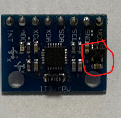
Picture of the sensor:
Meron:
This week, I worked mainly on the hydraulic support wheels for our motorcycle prototype, as shown in the picture and video below. These wheels are an important part of the prototype because they help keep the motorcycle stable while it starts balancing by itself.
I designed the support wheel system in SolidWorks, making sure it would fit well with the rest of the motorcycle frame. Because there was a long queue for the 3D printers this week, I decided to use the laser cutter instead to produce the parts more quickly. This helped me continue working without delays and allowed testing to start earlier.
The support wheels now keep the motorcycle balanced at the beginning, and when the system starts working correctly, the wheels can be lifted, as shown in the video. This is an important improvement because it allows the motorcycle to move toward full self-balancing functionality.
When the prototype is fully ready, I will integrate this system into the complete motorcycle and continue testing and improving it.
Week 15:
This is a big week for the both of us. We got a new motorbike to work with. We got it late, so it was not optimal time for us to test the system, With the tought of new weights. We placed the new parts inn and bought electronic wrap for cables As you can see in the picthure.

We optimized the code in MakeCode as discussed, where the delay was reduced — this can be seen on GitHub. Our main focus was achieving smooth operation. We removed the delay and changed elements such as basic.show_String to basic.show_Leds, where we manually created the symbols. We also experimented with reducing and increasing the bike’s speed.
Slow:
new version:
In this part, Salim worked on the controller and Mohammed worked on the driving logic. We spent a lot of time working on the code — it took quite a while. As you can see, we managed to achieve some balancing, but the weight was too high. The video shows the version with the weaker motor. After several iterations with wheels of different sizes, we concluded that the motor was simply too weak. As you can see in the video, we eventually got a new, stronger motor along with a motor driver.
//legg til egen del mo
We got to know the new stepper motor and driver which we had never worked with before. We got it to work.
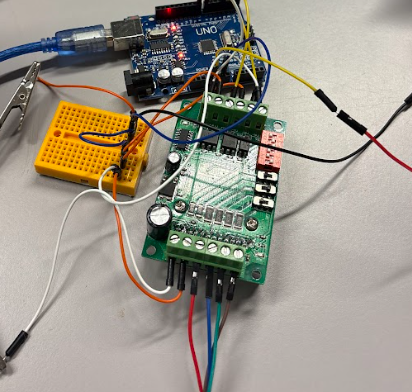
We found out that the motordriver was the reason for the wheel to spin so slow so we adjusted it by trial and error.
// forklar bedre
This was after:
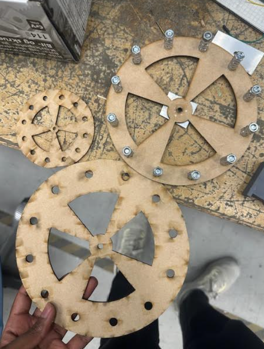
In this part did we use a big wheel for the bike with alot of weight and tested its speed and power this was used with bigger scrws:
As mentioned, the wooden structure started to wear down, so we fixed it using this solution:
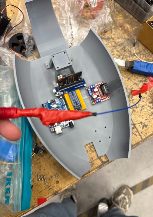
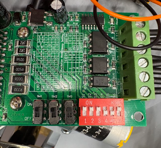
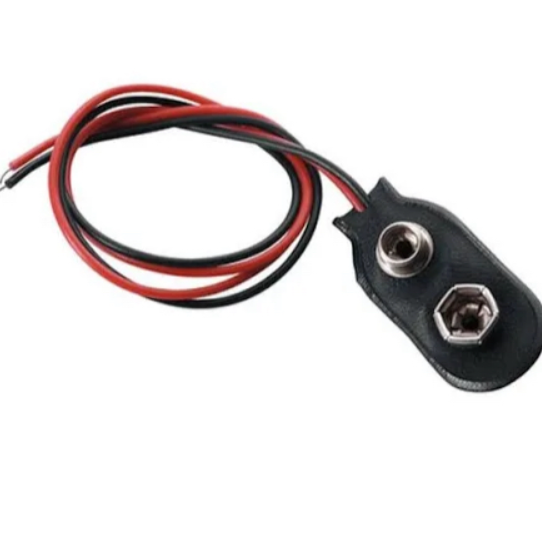
We had limited time to work on the KID values, and they will need to be adjusted again because a new bike is being built. This was also challenging because the wheel was not centered, although we eventually found a good solution. We plan to have this fully fixed before the final demonstration. On the last day, the battery charger stopped working, which meant we were unable to charge the main battery. The image is shown at the bottom. As a result, we had to buy 9-volt battery and a battery cable, and we soldered everything together. Some of the components were touching each other, which caused the IMU sensor to short out (also shown in the image). With help from Steven and Henning, we were able to fix the issue, complete the soldering, and get everything back on track.

We encountered several other problems along the way. One of them was that the motor overheated and stopped running. We also had to glue on a steel piece because the wooden part of the wheel wore down, which affected the acceleration. In addition, we had minor wiring mistakes that impacted the entire system and took time to troubleshoot and fix. We also had to familiarize ourselves with the new motor driver and make space for it within the limited room we had available.
We had limited time to work on the PID values, and they will need to be adjusted again since a new bike is coming. This was also challenging because the wheel wasn’t centered, but we managed to find a good solution for that. We will make sure everything is properly fixed before the final demonstration.
Reflection:
This was a fun and time-consuming project that we found very interesting. We learned a lot about how both software and hardware work together. We worked closely as a team and supported each other throughout the entire process. We had many frustrating moments, but we also learned a great deal. The best part was when we combined all our components and finally saw the completed product come together.
video of the final system we had a lot of problems that we couldnt resolve today in time that we will fix for the final presentation.
link to github with code
https://github.com/MuhammedOzdal/Self-balancing-motorcycle/tree/main
Meron:
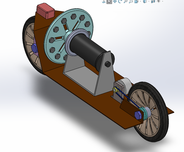
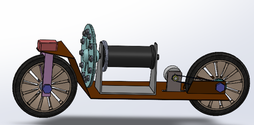
This week was mainly focused on completing the final version of our project design. Since Mohammed and I agreed that for this part of the project, we would focus on two different outcomes: Mohammed will continue developing and building the physical prototype, while my version will be delivered as the final design model. Since I have already worked on both Phase 1 and Phase 2, I spent this week working mainly in SolidWorks, finishing the last design details for the motorcycle, as shown in the picture below.
In addition to the final design work, I also focused heavily on the balancing system. I designed and printed around 10 different versions of the balancing wheels, each with different diameters and sizes. Throughout the week, I ran several tests together with the data engineering team to see which design worked best with the control system and software. This testing phase was very important because the balancing wheel plays a big role in how stable the motorcycle will be. By testing different shapes and sizes, we could better understand which design gives the best performance.
We also had plans to improve the physical prototype by changing its shape using carbon fiber in the composite lab. We contacted the lab supervisor, Kåre, to reserve time, but unfortunately, there was no free time available for us this week. We are hoping to get access to the lab next week so we can start working with composite materials and improve the structure.
Week 15:
Mohammed A
I worked on finalizing the scetches, 3D models, and changing some holes and adding more functionality to the bike. After sending desinge idea to the group, I startet 3D-printing the parts accordingly and finialazing some concepts for the prototype. After that, I glued the right parts together, made threads in the holes, and found the right bolts and nuts for them. We connected everything together, and I started taking notes on the feedback that was given, what I should add and where and on what I needed to focus on.
While designe suspention that would have beem mounted on the front of the bike and simulated as proper suspention. I worked on the and have been guided on how to build and what machine to use, and how to handle the parts. While it would have met my requirements for the self-balancing bike, some machines that were supposed to be used for the final touch had maintenance, which then dragged the suspnsion build past its deadline. While the maintenance is happening, I’ll be hoping for it to get done soon so we can implement it in Prototype 2.0
I was assigned to work on the Fases 3 and 4 of the motorcycle basically prototype 1 and 2. Due to some delayis in school 3D-printing, I got help from my brother and his 3D-printer and his knowladge in it. Back to the theme of phase 3. My solo focus was to work on the prototype and to try to overly engineer it as much as possible, and with the given knowledge of what should be put in electronics, to what type of motors and servomotors and wheels. My primerly focus that was mentioned to me was to make the motor stand tall, with enough space for the gyro wheel to spin and to be able to withstand the viberational force and impact. The bike had just enough space for the given components, motor, I have met the groups requirements for the bike especillay focusing on the next of the back since the last one was flimsy.
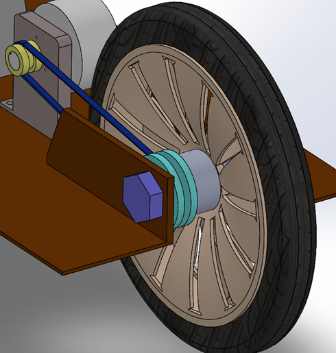
I started working on the chain and cogwheels for the back wheel and back motor. After multiple calculations and failures on the equations and 3D-printing the parts, I finalised to a more suitble designe, calculations, and teeths for the cogwheel to move the chain forwards and back. Which then met its own setbacks when I added it to the prototype. The wheels and chain are made using PLA “plastic” that is a standard, but in the settings you can choose its strongest durability, and assuming that they will be put into tremendous amounts of stress and strain, I let my brother know that it should be made at its highest durability in that plastic.
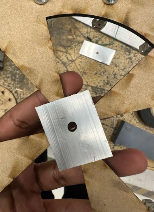
After making the chain, I focused on making a D-hole washer for the two new motors. I worked using aluminium plating and carefully drilling the right holes in the right places. It’s a tedious process, but the simpler one to make was for the big moter since its circluar shape was 5mm and the D-line was 4,3mm from the end of the circle. The other motor required more precision since its circulare shape is 4mm, and the line is 3,4mm. Through trial and error, I succeeded in finishing both of them. Though that didn’t promise great results in the end run, since the shaft slowly scraped off the hole shape. I’ll be trying to use a steel plate and hope it shows better results now and in the long run. Return to the aluminium plate, the plates are small, so and the best decition for testing was to just glue it to the wheel that would be tested on. I am planning to go from small plates to actually making the wheels in their designated material, hopefully steel.
I created a design for wheels that had been manufactured and delivered a couple of days ago. They will give the prototype a challenge to balance and to drive back and forwards. The group doesn’t have any feedback on it, and the wheels do work as intended. I didn’t calculate that one of the wheels should be one part and without a wheel bearing, so that the connection between the motor and the wheel would have been easier. Both of the wheels ahve wheel bearings, which added more work on managing to do a propper connection between the cogwheel and wheel. After some thorough thoughts, I made a circular object with that has two pins that stretch out and the up just high enough for the feets to fit inside the cuts in the wheel. That “thing” is then glued to the cogwheel. That in itself is enough to rotat the wheel when the motor is working.