The final blog post has finally arrived, and looking back, it’s a bit surreal to realize how far we’ve come. Fourteen weeks ago, we set out with a simple idea: build a working PickMeBot. At that point, it felt like a huge challenge, and we honestly didn’t know how many unexpected problems and late-night debugging sessions were waiting for us along the way. Some parts of the project went smoother than expected, while others turned out to be much more difficult than we imagined. But in the end, and as you’ll see in this post, we actually managed to build the robot we set out to create. This final entry will wrap up what we’ve achieved, what we learned, and how the whole journey came together in the last phase of the project.
Sondre:
This week, Theo and I worked closely together to finalize the integration of the two main parts of our system: my PID controller and heading correction, and his A* algorithm for maze solving. We started the week with a frustrating issue that made it look like the robot was somehow damaging the side sensors. We tested several software-based fixes, but nothing helped. Eventually, we asked Robin and Anette to check for electrical problems, but they couldn’t find anything wrong either.
We then asked Steven for new sensors and replaced the old ones, hoping that would solve the issue. Unfortunately, the problem persisted, the sensors still returned either -1 or no readings at all. After hours of debugging, we finally discovered the real cause: the power bank we were using was delivering unstable power. Once we swapped it out, everything immediately started working again. This was a huge relief after a long and confusing troubleshooting session.
Improving the Heading Logic
With the sensor issues resolved, we could move on to fine-tuning the PID controller and the heading correction system.
At the start of the project, the robot handled rotations by reading the heading before a turn and then adding or subtracting 90 degrees depending on whether it was turning left or right:
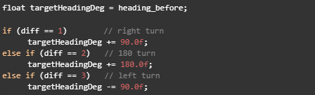
This approach worked most of the time, but small IMU inaccuracies accumulated after several turns, causing the robot to drift away from its true heading.
To improve reliability, I reintroduced a more stable heading method from my original implementation. Instead of relying on the IMU for every turn, the robot now uses a steps counter to track how many 90-degree rotations it has made relative to the start heading:
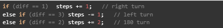
The target heading is then calculated like this:

This made a significant difference. Instead of relying on potentially noisy IMU readings for every turn, the robot now uses a consistent global reference based on how many 90-degree steps it has completed. This resulted in much straighter driving in corridors and more reliable navigation through consecutive turns.
Fine-Tuning the PID Controller and A* Movement
Next, we fine-tuned the PID variables that control both the robot’s heading and its distance from the wall. We quickly discovered that even small adjustments had a large impact on how the robot moved between cells. This happened because the distance between grid cells in our maze is based on time, not direct distance measurement.
Since a mecanum drive mixes forward motion, strafing, and rotation, strong PID corrections caused the robot to drift sideways or rotate too much. When that happened, the time-based movement no longer matched the actual physical distance.
By adjusting both the A* parameters (which determine how long the robot moves per cell) and the PID variables (which stabilize heading and wall-following), we eventually achieved reliable movement. The robot now stays centered, maintains a straight heading, and consistently reaches the next cell without drifting off course.
Adding the Arm Pickup Sequence
The final step in the project was adding the arm pickup sequence. Fortunately, this part was much easier than the previous steps since we had already created a dedicated ArmController library earlier in the semester. Integrating it into the main program was therefore straightforward.
At the final cell of the maze, the robot lowers its arms, drives forward to pick up the box, lifts it, and then begins navigating toward the drop-off point. Once it reaches the destination, it lowers the arms again to release the box. With this final sequence in place, the robot can now complete the entire task autonomously: navigating the maze, collecting the box, and delivering it to the specified location.
Link to Github final code can be found here:
https://github.com/thgheysens/smartSystem3
And final video of the robot can be seen here:
https://youtube.com/shorts/sKD6PZypX0Y?feature=share
Theo :
This week, Sondre and I finished optimizing the code so that our car can move as accurately as possible. This allowed us to add the puck pick-up ability. We initially faced some issues with the sensor; it appeared that there was an overvoltage on some pins, so we had to replace the damaged sensor. I also added two new specifications to the car. The first one was to integrate the pick-up code into the navigation system. Now, during the last move, the car checks whether something is loaded or not and adapts its final action accordingly. The second specification allows the car to return to the origin point if no path is available. With all these functionalities implemented, we were finally able to achieve a perfectly working project that meets all our initial objectives. In the video Sondre posted, we can see the car going through the 4×4 maze, testing a path, detecting that it is not available, then calculating another one, picking up the object, and going to the delivery zone. After that, we also tested the car in a 5×5 maze, and it reached the destination without any issues.
To summarize my work: I started with the use of the sensor, then worked on the arm and its calibration. After that, I centralized the movements in one file and implemented the A* maze solver. Finally, I worked with Sondre on optimizing all the movements.
Anette:
This week has been busy. I used the power profiling kit to test the nrf52832 board I borrowed from Steven, finished the battery pack with the help of Øyvind from group 7 and compiled a summary of my previous work on the pcb. I also started writing a summary of everything I have done until now that Im going to add to the USB stick later. Furthermore, there is now less than 2 weeks until the presentation, so my main focus will now be to connect the battery pack and to work on the presentation.
Battery:
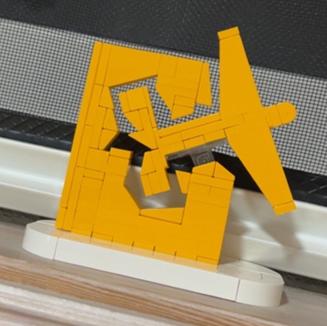
As mentioned in the last blog post the batteries had to be ordered quickly due to unforeseen circumstances. I made a plan with Øyvind to make the battery pack on Thursday (because we both had an exam on Wednesday), but we ended up moving it to Friday after they arrived late due to a free lego set (they were supposed to arrive earlier in an envelope but instead came in a package late on Thursday). Since this is kinda funny, here is the lego set:)
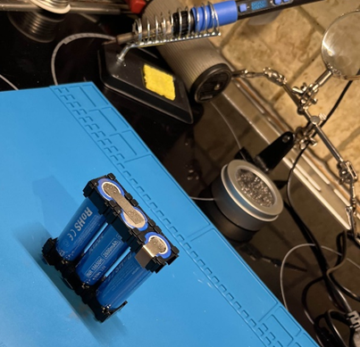
Since Øyvind has made a battery pack for his project as well and is familiar with the process, he was kind enough to help me and let me borrow the equipment I lacked to make it. The first part was relatively easy. The plan was to use 3 of the batteries and use a premade BMS Robin had provided me with. First the batteries were secured in place, before metal strips were spot welded on to connect the batteries in series.
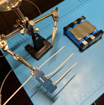
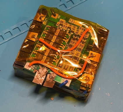
Then more strips were spot welded to the connection points between the batteries and the BMS (B+, B-, B1, B2). Tape was added to the side of the battery pack to keep the BMS board secure and prevent friction damage. Cables were soldered to the BMS board, then to the battery pack as seen in the pictures below. Then an XT60 cable was soldered to the output of the BMS. This was a challenge due to the size of the cables. When soldering, the cables stole all the heat from the soldering iron, and therefore made it challenging to attach them to the board. After a few to many attempts they were connected and then taped, before the BMS itself was taped with kapton tape.
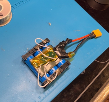
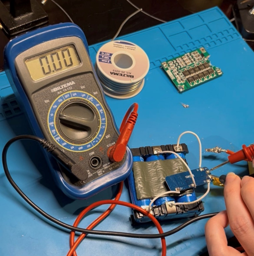
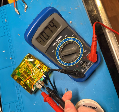
This is when the challenges began. After beginning to wrap the battery pack we decided to test the output to see if it worked. It did not work, so we started testing to see if we could detect the error. The first error was easy to spot, the soldering on one of the outputs had disconnected. Before reconnecting everything, the board was tested to see if there were any more errors. It was then discovered that the BMS itself didn’t give any output. When testing the other points on the BMS, all of them had the expected voltage, but after some more error detection we decided to use the backup BMS Øyvind had (the green one in the picture).
The new BMS was broken and had a missing chunk where the input and output soldering points were supposed to be. It also had a lot of old soldering on the other points that needed to be removed. Other than that it was seemingly completely intact. I used some time removing the soldering since the cables had been soldered through the holes and the rests of the cables also had to be removed. Since the metal of the soldering points were gone the next challenge was to connect the input and output to the cables. This was more difficult than expected, especially on the negative side due to the lack of metallic points, so the solder didn’t stick to the board. To make it easier we used some of the metallic strips from the point welding and soldered these to the board. After many attempts they were finally connected, and the battery was tested and wrapped in kapron tape. After this the negative point ofc fell off, but we didn’t have time to fix this at the time because it was getting late.
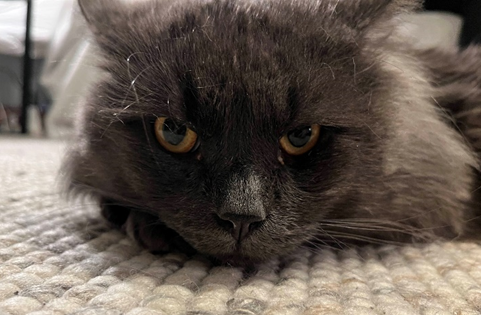
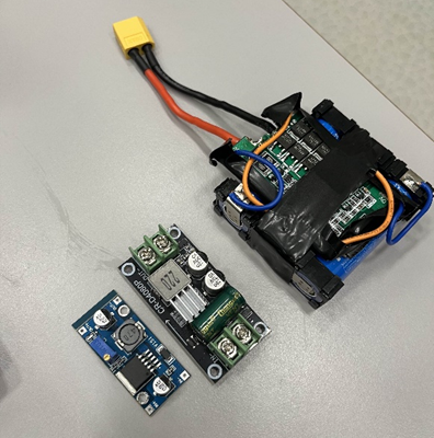
Later I then tried to solder the point back on before soldering on the XT60 cables again. When doing this I realised it did not want to stick and because of the tape it was hard to reconnect it. Furthermore since the points were close together it was hard to do this at school without shorting the battery. Also the metal was hard to hold with the lack of equipment there. After a few attempts and a lot of struggle, I called for a backup opinion. It was way to late at this point to order a new BMS, so the only choice was to find a new one or fix the old one. After talking to Ivan (from previous smart systems group) I ended up going to Daniels (also previous smart systems group) for help since he had tools and previous experience in fixing electronics. After looking at the board he said its fixable but also noted the trace to the protection circuit was broken. He then proceeded to help me by scraping of the protective layer of the board and soldering the broken point to the protection circuit, plus scraping a bit of the traces of the output points and connecting the cables directly to the board. I don’t have a picture of this but I do have a picture of his cat Chappy that was a big help in this process. When soldering he also noted the sides of the pcb sparked when touching the soldering points of the batteries, so he taped the edge to prevent this. This is then how the battery pack looks now. I also have 2 buck converters, one that is adjustable that I borrowed from Øyvind and one that has an output of 5V that I borrowed from Daniels. The last step is now to connect the battery to the car and find a place to store it since its too big to be placed where I originally planned. I also need to talk to Øyvind (if there is time) if he can help me tape it again since the tape was removed in the process of fixing it.
Testing:
Since I didn’t have time to finish and order the Microcontroller in the few weeks I had, Steven gave me a similar board I could test. The board he gave me is a development kit for nrf52832, which is similar to the nrf52833 I was working on previously. I also got the Power Profiler Kit II that I used to test the board.
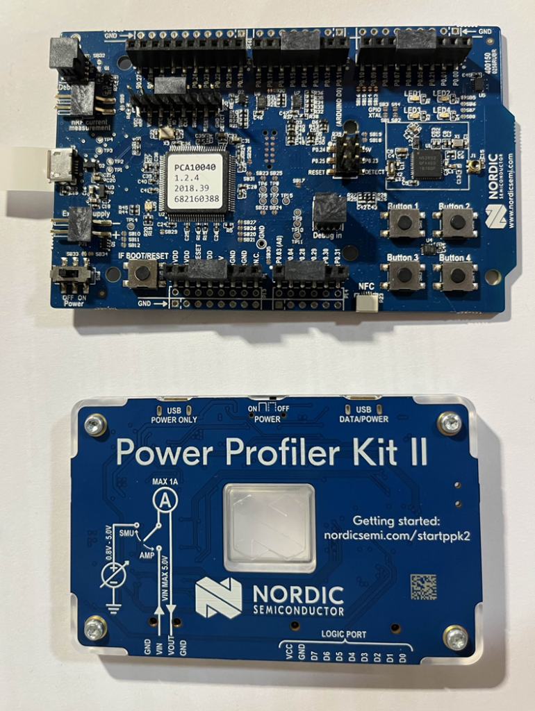
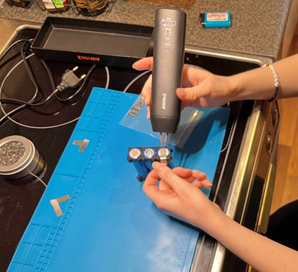
To use the board I had to use the “nRF Connect for Desktop v5.2.0” that I downloaded from the nordic semiconductor website, and I used the “Power Profiler” app. The Power Profiler II can be used as either a power supply or an ampere meter. I started by connecting the board as shown under.
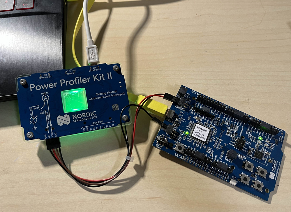
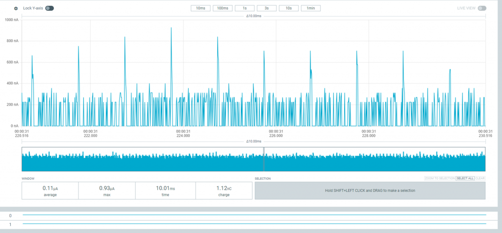
When connected the light of the kit turned green. Then I selected the PPK2 board, and chose the ampere meter mode, which turned the board blue. I used the sample function to sample for 1 minute. Under you can see the results I got. The first picture shows the layout of the entire program with the window showing the sampling results for 1 minute, and the second picture shows a sample of 10ms.

PCB:
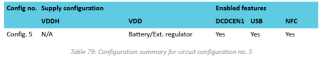
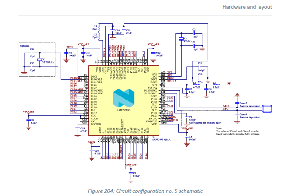
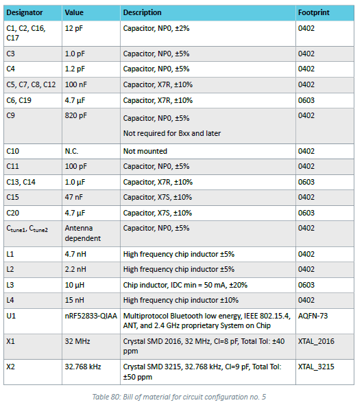
The PCB has been the biggest challenge this semester. Mostly because I was struggling to collect information and resources from the beginning to know where I should start. I started working on this a few days before halloween, and quickly realised this was not going to work. I used the first 2 weeks trying to wrap my head around it and comparing what we needed from the board vs what we already had, reading up on relevant information from the datasheet and compiling what we would need on the board itself. Steven advised me to use a lot of test points in case there were errors, and to have both usb and external power supply. Also part of the challenge was that the board should contain an NFC antenna. To know what kinda pins we needed I talked to Sondre, who gave me the information we had then. The only problem was some uncertainty around the motor controller, since we didn’t know what kind of pins it needed, and then didn’t know if we needed to change anything. When we finally got the information we realised there wasn’t enough space to connect it, partially because the microbit already has a built in motorcontroller. After a lot of research I found this circuit from the datasheet that I could use for the chip I had (nRF52833) on page 845 (7.3.5 Circuit configuration no. 5 for QIAA aQFN73). and the bill of materials.
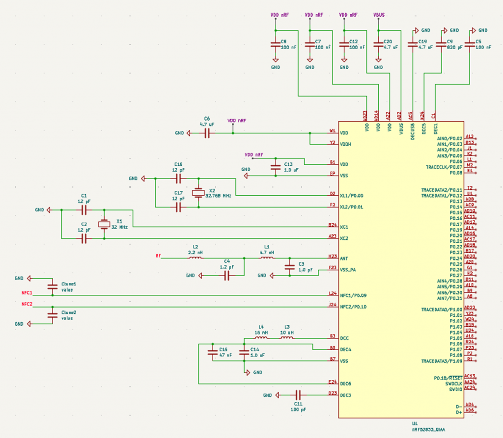
I then tried using this to make the circuit in OrCAD, and this is where the problems began. I couldn’t find the footprints for the nRF chip in OrCAD, so I tried finding it on the nordic website with no luck. It didn’t help that I had to re-familiarize myself with OrCAD since I haven’t used it since last year. Additionally I don’t have any experience making PCBs except for the subject I took last year, so I didn’t know where I should look to find footprints, and I didn’t learn this before later in the process. Therefore I started trying to make my own footprint for the chip in OrCAD. This proved to be difficult and hard to keep track of, and after a while of trying the program stopped working because of licence issues since I activated it last year. I then ended up giving up and switching to KiCAD, and I quickly realised I should have done this from the start, because KiCad proved to be way easier PLUS it already had the footprints for the chip, so I could have saved A LOT of time if I had known this earlier. I then made the circuit from earlier as shown below, and I used the footprints from the table. Most of them were already in the preexisting library, except for the crystal oscillators. I ended up trying to find some with the same value on digikey. Then I proceeded to find the footprints and downloaded them from snapeda (SnapMagic). What I didn’t realise was I didn’t need to do this because the XTAL_2016/3215 refers to a general footprint for the crystals, which I didn’t know. The circuit is also still missing the antenna because I didn’t know if I should use an external antenna or a built in one and I couldn’t find any information on it. Also this circuit is just the start of the PCB, but I didn’t find the documentation for the rest until a while after I started. I was going to use the documentation for the nRF development kit with the right chip to compare what I needed for the rest, but then I ended up working on the battery instead.
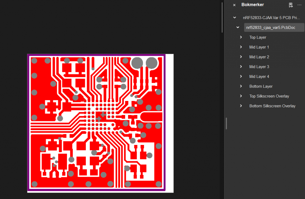
Also, my last 2 problems: Since the chip is so complex, there are no premade pspice models for the chip. This meant unless I made my own it would be impossible for me to simulate the circuit. I tried looking into if it would be possible to make my own, but this is a complex process that I did not have time to attempt. I was therefore advised to use a preexisting circuit. The problem here was I kept finding a lot of conflicting information. An example of this was: when I looked into the layout I found this document that said I needed 6 layers for the PCB, but later I found out I only needed 4.
Robin:
Initial Electronic Integration
From the beginning of the project (Week 3), it was imperative to correctly model our components to design a coherent electrical system1.
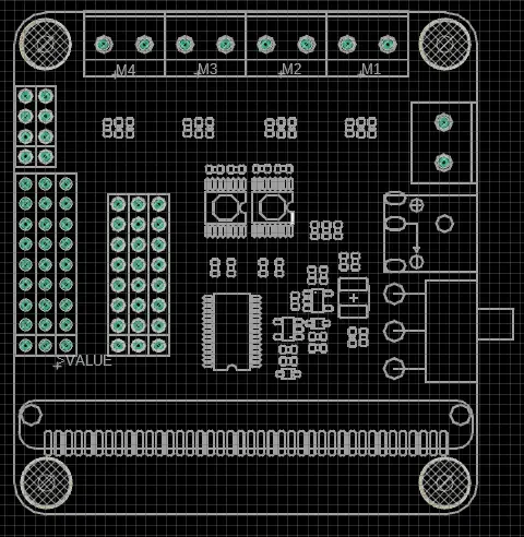
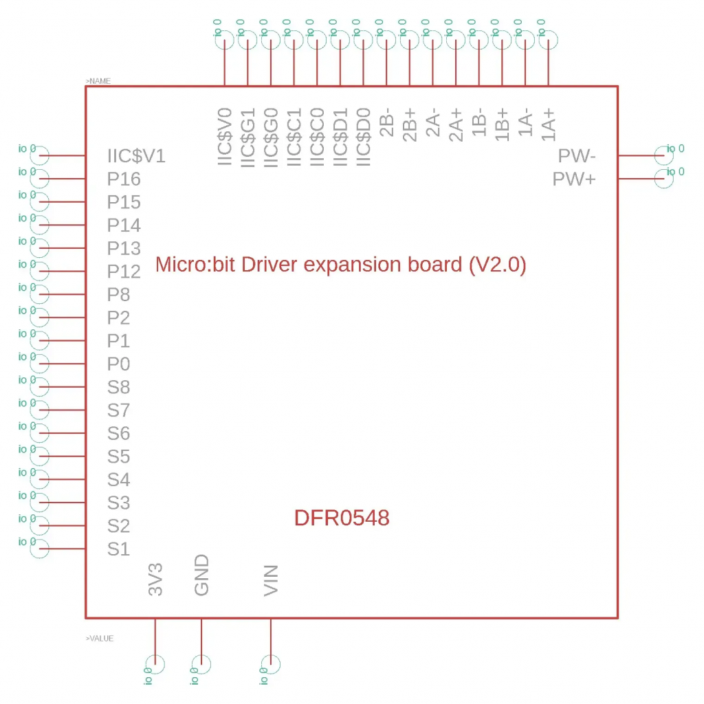
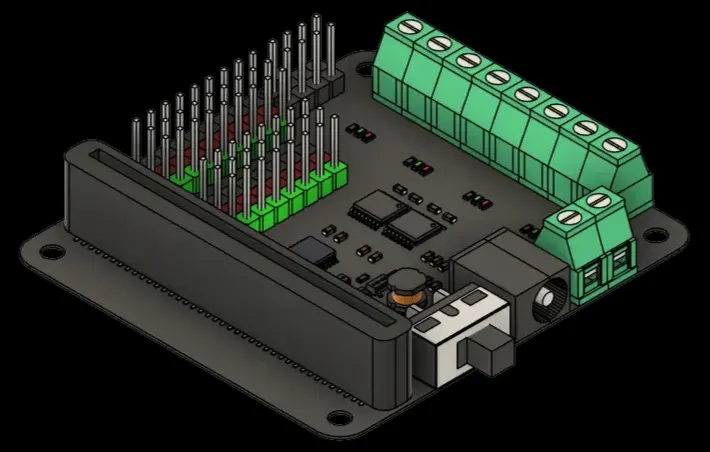
Library for the “Micro:bit Driver Expansion Board (V2.0)”
The motor expansion board did not exist in our CAD software. I therefore created a complete library based on the DFRobot technical documentation 2.
- Footprint: Precise definition of dimensions and connectors for the PCB3.
- Schematic Symbol: Logical representation of connections (I2C, PWM, GPIO)4.
- 3D Model: To visualize the final mechanical integration5.
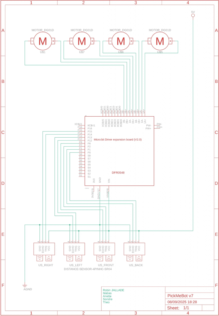
First Robot Electrical Schematic
I then produced the first global wiring schematic for the robot. This document served as a reference throughout the project for connecting the 4 DC motors and the 4 ultrasonic sensors (HC-SR04) to the expansion board 6.
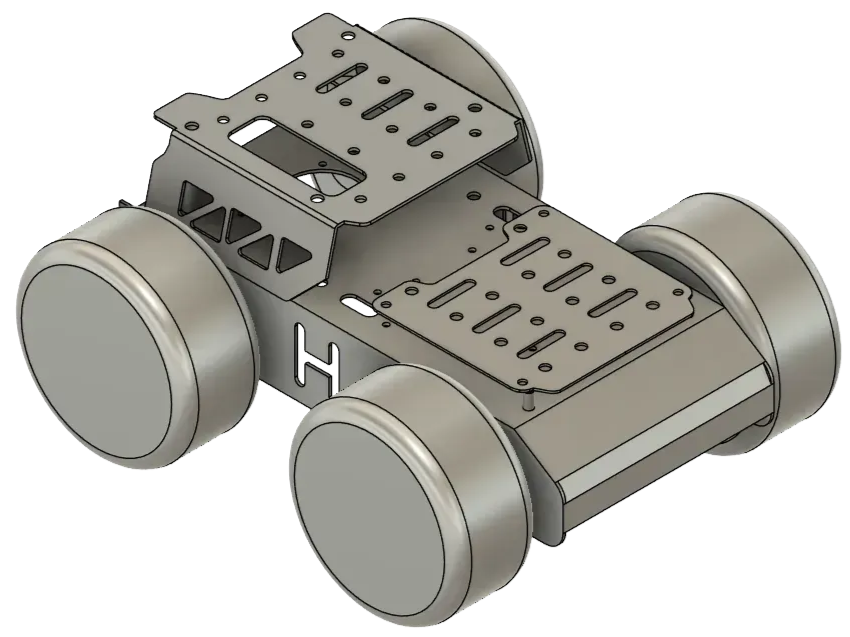
Mechanical Design (CAD)
Lacking a dedicated mechanical engineer, I took charge of the modeling in Fusion 360 to adapt the chassis to our delivery needs.
Chassis Modeling
To validate the component layout, I modeled the car chassis in 3D by calibrating reference photos to a 1:1 scale7.
Robotic Arm Design
The lifting system evolved to gain robustness and precision:
1. Integration of Threaded Inserts (Week 7): To avoid damaging the 3D printed parts during frequent assembly/disassembly, I redesigned the servo mounts to integrate brass threaded inserts. I used digital calipers and a ruler to ensure perfect tolerances 8.

2. Final Design (Week 8): We moved away from the idea of a lifting tray. I designed a specific gripping system where the arm grabs a custom box equipped with side handles, which is much more stable9.

Power Electronics: BMS and Charger
To transition from a prototype powered by a Powerbank to an autonomous robot, I developed a power solution based on 3S Li-Ion batteries10.
Battery Management System (BMS)
Lithium battery safety is critical, so I designed a BMS to protect the cells against overvoltage and deep discharge.
- SPICE Simulation: Before freezing the design, I simulated the protection circuit in SPICE to verify the behavior of the MOSFETs and voltage thresholds.
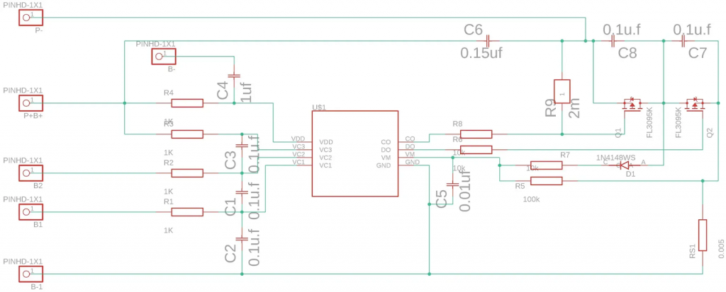
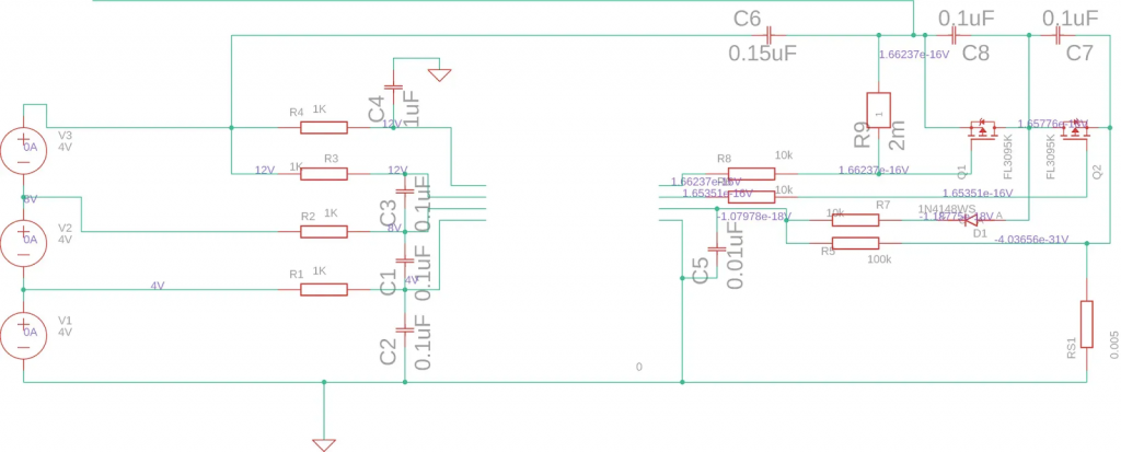
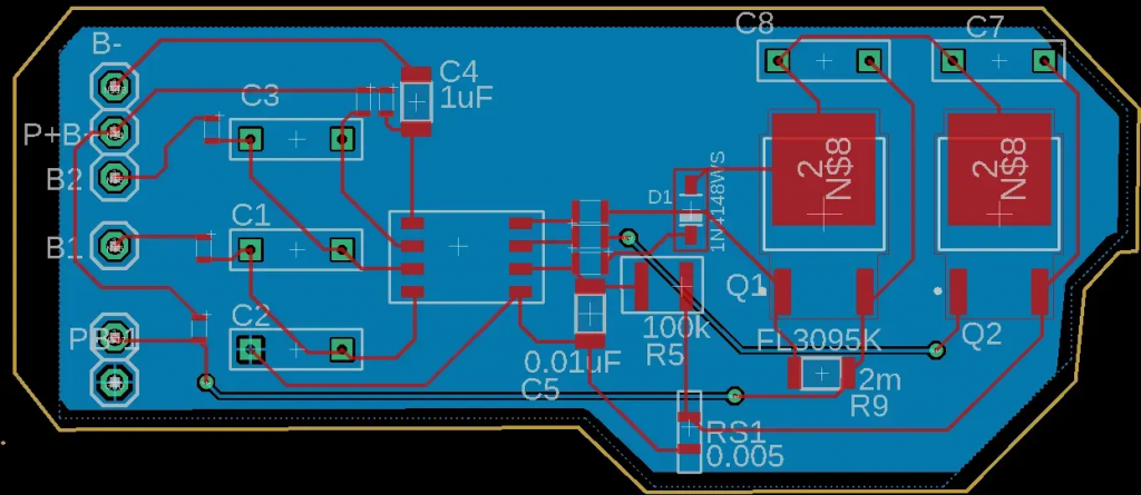
- Schematic and PCB: I then realized the complete schematic and the PCB (Printed Circuit Board) routing. I performed a 3D collision check to ensure components fit well on the board 11.
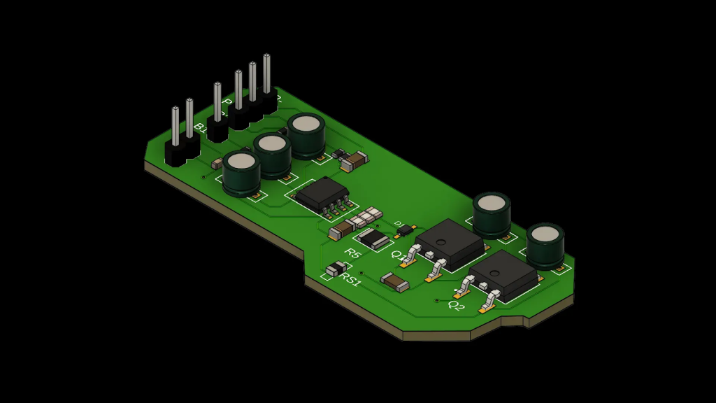
“Step-Up” Charger (5V to 13V)
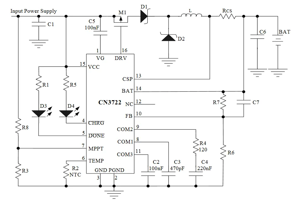
At the end of the project (Week 13-14), we had to adapt our charging strategy. Since sourcing 13V chargers was difficult, I designed a voltage booster circuit (Boost) based on the CN3303 controller. This allows charging the 12.6V (3S) battery directly from a standard 5V USB source 12.
Dimensioning Calculations: 13
- Target voltage $V_{bat}$ : 12.6V.
- With $R6 = 10k\Omega$, I calculated $R7 \approx 91k\Omega$ (adjustable via potentiometer) according to the formula:
- $$ V_{bat} = 1.205 \times (1 + \frac{R7}{R6}) $$
- Charging current set to 1A via a current sense resistor $R_{CS} = 0.12\Omega$.
Conclusion
This semester allowed me to cover the entire hardware development cycle of a robot: from creating virtual components (CAD libraries) to complex mechanical modeling, including simulation and routing of power electronic boards. The final robot now features a clear architecture, reliable mechanics, and a custom-engineered power solution.
Matias;
This week has been a bit busy for me due to exams and travelling, so I wasn’t able to dedicate as much time to the project as usual. Even so, it felt like a good moment to look back at everything we’ve done and what I’ve learned throughout the entire process.
Over the past weeks, I’ve gone from designing schematics in Capture to almost completing a full PCB, and eventually adapting the plan to a protoboard solution when the manufacturing costs turned out to be too high. This taught me how important it is to stay flexible and make practical decisions when constraints appear.
I also learned a lot about active filters, PWM smoothing, and how filtering directly affects motor behaviour. Working with Sondre on the signal tests and using the Analog Discovery helped me understand waveform analysis much better. On top of that, testing the step-down regulator, preparing the BOM, routing the PCB, and evaluating different design approaches gave me a much clearer understanding of real-world electronics design.
Even though this final week was a bit lighter because of personal commitments, the overall experience has been very valuable. I’ve improved both my technical skills and my ability to adapt, troubleshoot and collaborate. I feel much more confident now in moving from theoretical circuits to practical, working prototypes.