Hello and welcome back!👋 This week was time for final integration. See individual parts before integration at the top, and the section about integration in the second half. It has been fun!
Fredrik:
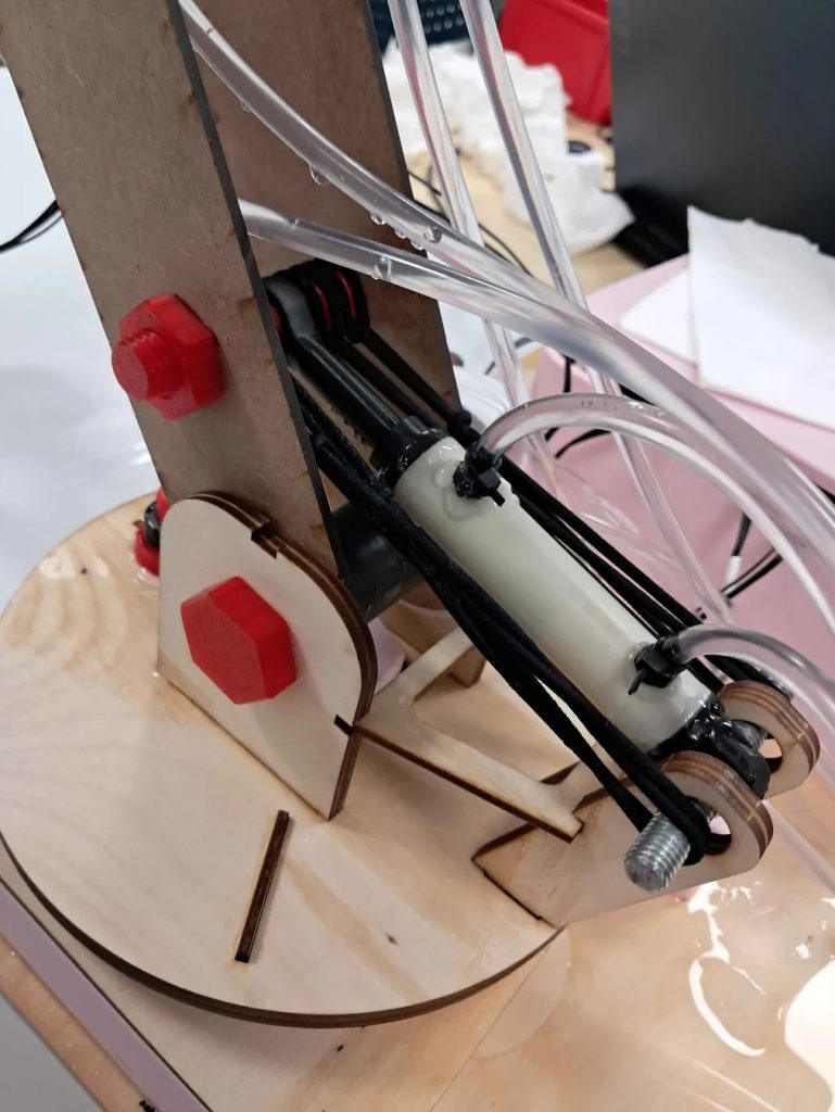
For the final weeks of the project, I have primarily been working on the hydraulic system, trying to figure out how to keep it sealed. Last blog post, I mentioned some mitigating efforts I would include in the design of the next cylinder, in order to keep it from leaking. These were mainly three things: more o-rings, 100% infill in the prints, and simply applying a LOT of glue. So after another round of printing, drilling and gluing, the new and improved cylinder was done. I will let the video of the test speak for itself:
The test was a great success. There was finally almost no leakage from the cylinder. This means we are good to go to implement the cylinders into the system.
The last couple of days I have been working hard with Syver to troubleshoot and iterate on the system. Check out the common part to see how that went.
Lisa:
The last blog I wrote about implementing some final touches in the software, leaving it to hardware to integrate so that we can verify functionality. This left little software work to do before helping with integration. Besides this, I also needed to work on some other courses, taking some time away from work before final integration. For the final integration, I helped filming and creating the video, as well as general assembly and debugging when needed.
Syver:
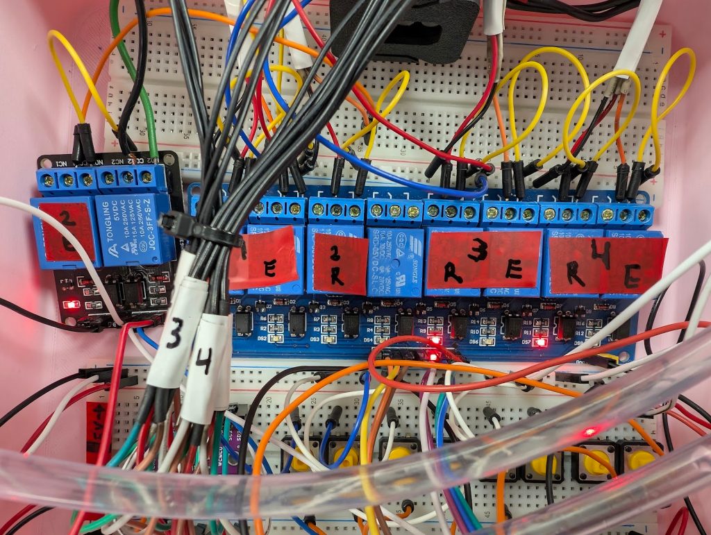
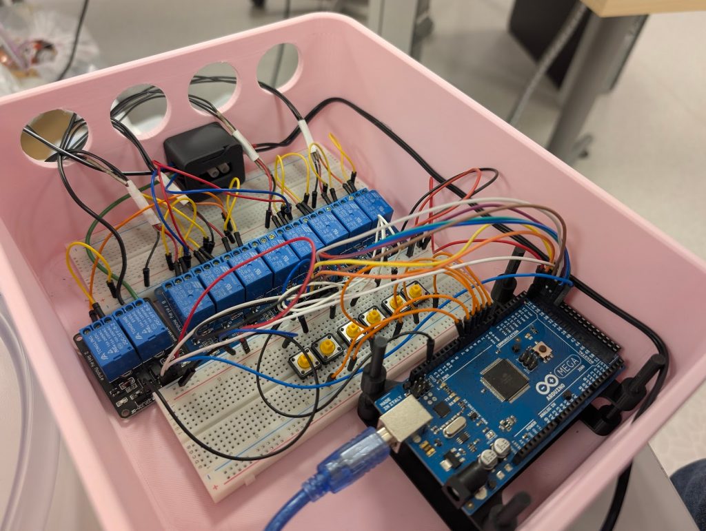
For the final week, we needed to integrate the system. It ended up being a journey filled with frustration, perseverance, and copious amounts of shoddy debugging using AI. Since last time I wrote, I’ve been mainly working on the electronics, connecting everything together and tidying up the electronics box. Before integration, only sensor circuitry remained. These were the results;
Other than this, I’ve been tidying up the repos, doing some julevasking. This was mostly in the kinematics repo, getting it ready for integration. This is where I stopped working individually, and started helping the others with integration, mainly working on electronics and Web UI integration/debugging. See the bottommost section of the blog. 🙂 This project has been extremely fun and educational, getting to work with structured and large C++ projects, and doing some work bleeding into electronics with EMI-squashing and such. I believe that the project as a result couldn’t have been done without the structured engineering approaches within both software and hardware, and that, I am very proud of.
Emory
For the final week of the project, I did not work actively on the project as the parts I worked on were done, and I had upcoming exams I needed to focus on studying for. During this period, my main contribution was observing several tests performed before and after the system was fully assembled.
Erling:
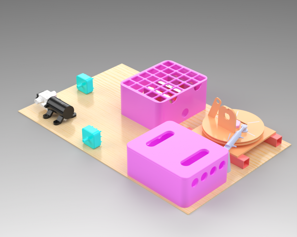
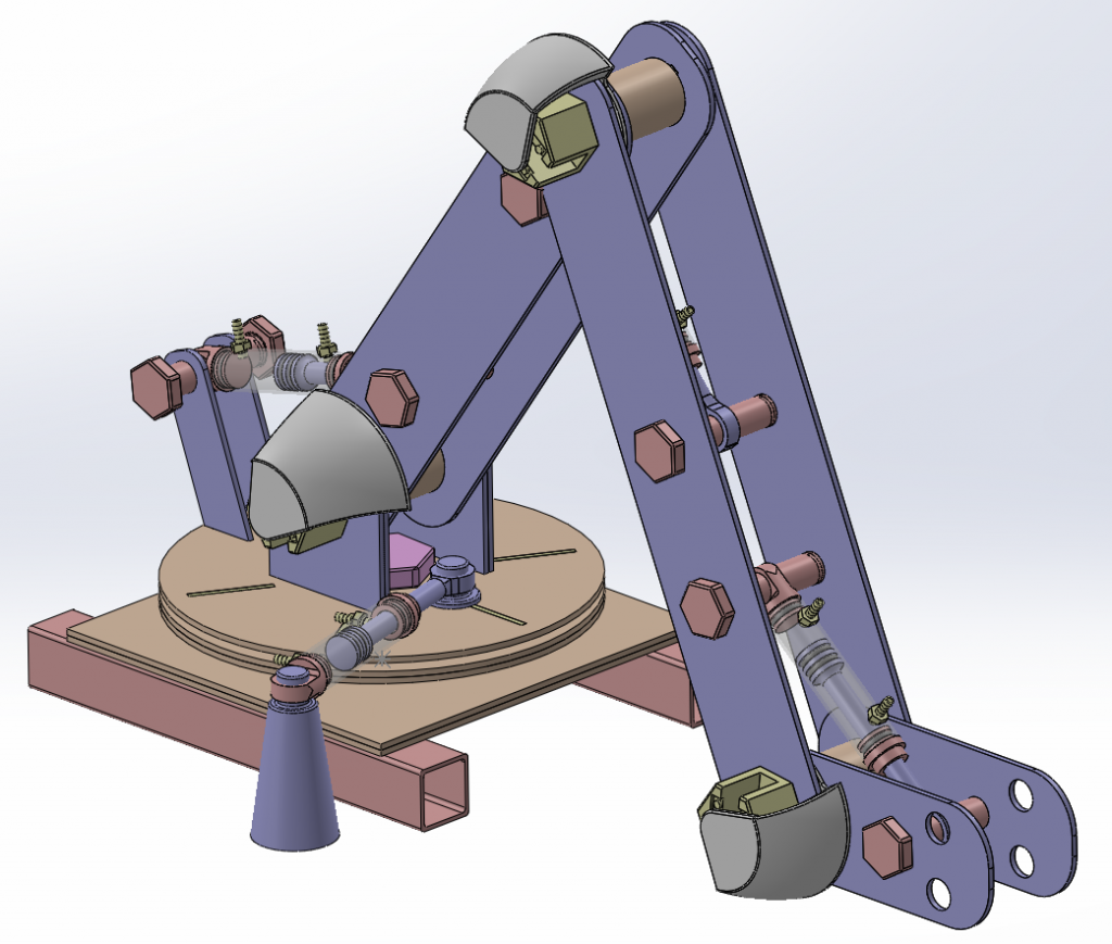
I started by assembling a model in Solidworks of how the whole system should look in the physical world. I only had the model of the base locally at the time, which is why the arm isn’t complete in the image. This illustration was meant to give a sense of how it all would look in the end, as we had not really organized the system too nicely during testing yet.
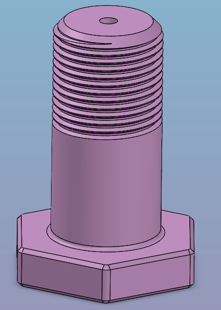
In the previous blogpost, we found a way to mount a cylinder in order to control the axis, but we had not yet found a good way to read the angular position of the Azimuth joint, the rotation axis of the base itself.
In order to read this parameter, we decided to use the same encoders as are used on the other axes, and read the position with a magnet placed over the sensorboard we already had a few units of.
This measurement is important is measured on the axis of rotation, to achieve this, I made a change to the center bolt in the base structure so that we had a place to embed the magnet. To hold the sensor board, i modeled and printed a cradle to fit under the bolt in the base. i got the peg pattern from Fredriks design for the similar sensor holders for the other axes, and made a few different versions of the design with different distances from the bolt end. This was important because i measured a difference in the realworld version of the base and the theoretical version in CAD. I made four versions in 1mm increments to be able to pick the one that provided the best distance from the magnet to the sensor chip.
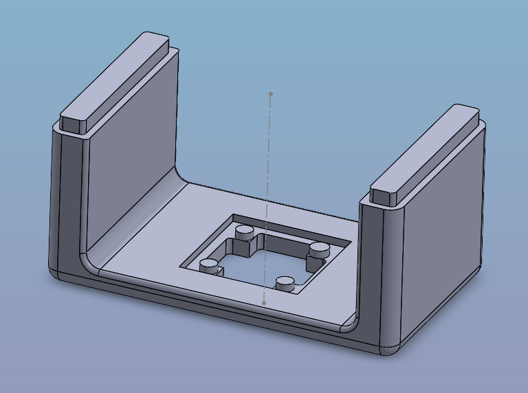
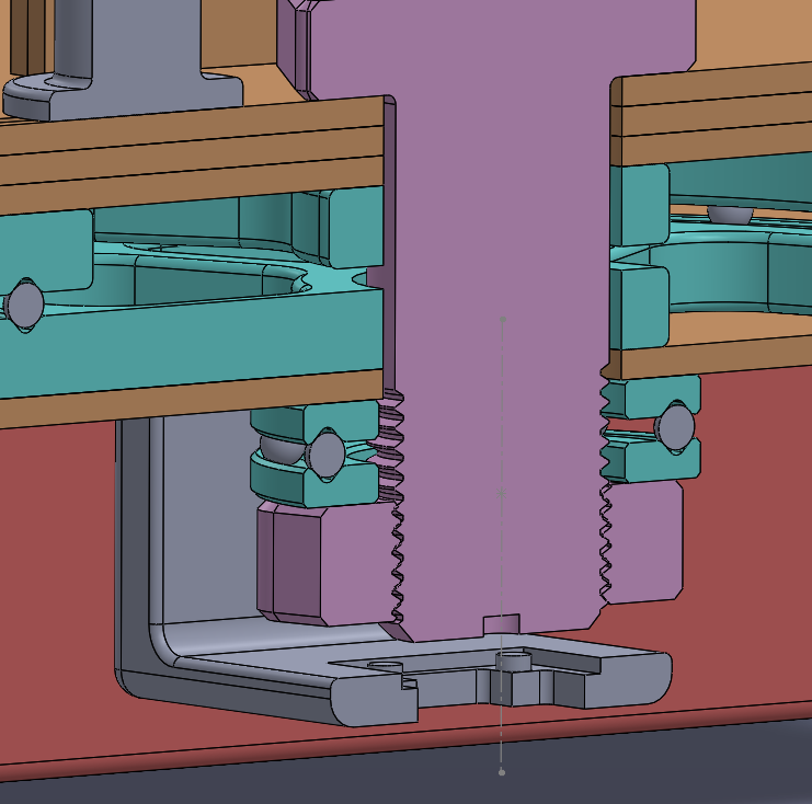
This seems to work adequately for our purpose, and integrates previously uses components, reducing extra work in implementing the sensor in the computer guidance system.
Gjorde endringer i basen til armen, dette for å tåle belastningen i strekk på J1 under operasjon.
After a bit of testing, we realized that the base wasn’t really strong enough to sustain the loads put on it by the movement of the arm. This made it necessary to do a small redesign and add a little more functionality. The strength requirements as well as the need to mount a sensor and the magnet, I made the following changes.
– New baseplate to hold the encoder cradle.
– Changed the the profile on the beams.
– Made the top structure of the base a bit stronger.
– Made the connetion to the shoulderplates for the arm stronger.
– Added a brace between the anchorpoint and arm for joint 1.
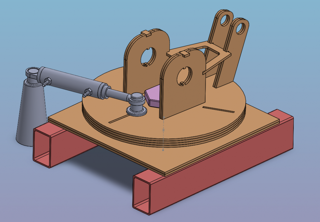
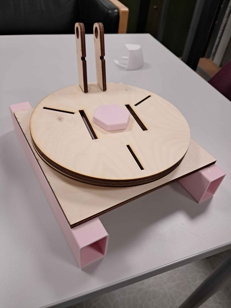
In all, after the changes, the base looks like this:
after reprinting and laser cutting the new parts, we assembled the new base and it looks like this. In the image below, the base is lacking the shoulder plates and the brace, these are added when the arm is mounted to the base. This can be seen in the other sections of the blogpost.
Integration joy
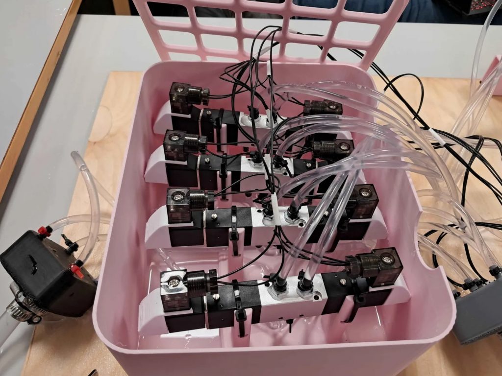
Now with the system fully designed and components produced, it’s time to implement, test, and hopefully get it working. With a layout defined, we could start implementing the components. Mainly that being the electronics into the electronics container, and the valves into the valve container.
Getting the hydraulic system ready was quite the task. We attached every valve connection to the valves, every tube to the valve connections, every valve to the valve mounts, and glued every valve mount to the container. While doing so, it was important to thread the tubes through the openings on the container, separating between input and exhaust. This made tube management way easier later. The tubes were then attached to the manifolds, where the input manifold went straight to the pump, and the exhaust manifold went right back into the bucket. Then finally, the output tubes were attached to the cylinders, making the hydraulic circuit closed.
With much of the electronics already assembled into the electronics box, the rotary sensors and the I²C multiplexer remained. Using bundles of cables we made earlier that were cut to the correct size, made the process pretty straight forward, with little to no cable mess. We had some trouble attaching the sensors properly to the arms without connective issues, but some reseating and hot glue fixed most of the problems.
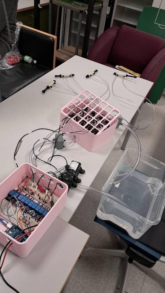
After the setup was complete, we did a full hydraulic test to verify that the system worked as intended. That means testing how the pump, valves and cylinders work together, while being manually controlled by arduino. We have attempted this before, but ended up not being successful, as everything was leaking and it was hard to control. But now that we are at the end of the development process, and we have fixed a lot of the problems from the previous test, we ended up with a successful test. All the cylinders worked as intended, and controlling them was easy.
With the successful hydraulic test done, we could start implementing the system on the arm. The full 3d-model of the arm (with slightly outdated base) can be seen in the picture below. It was exciting to see if the cylinders could carry the weight of the arm, and how hard it would be to accurately control it. As you can see in the video, the test was definitely a success, meaning that we were good to go to implement the sensors, and having the system be automatically controlled based on the sensor-data.
With that, integration hell started, both on the software and mechanical side. Many days of iterating, troubleshooting and praying that our solutions work.
With much of the software ready to be tested on the real hardware, we needed to integrate all the electronics to match. This led us on a journey of integration issues. Our main issue is that there were a myriad of electronics related issues, and none of us were electronics engineers. At first, we approached the problem of random interrupts triggers, with no explanation for why they went off. Making the button press-and-hold to activate was but a band-aid on the issue, as it didn’t solve the big underlying one.
The main issue was LOTS of EMI radiating from the relays, which we spent days trying to debug. We had no experience using coils in circuits, so we neglected the use of flyback diodes. After tracking down some, we placed diodes on the coil related circuits, of which we have 9, counting the solenoids and pump. This reduced all the random freezes we experienced. Another issue was that water got on one of the sensors, leading its already floating direction pin to spasm. This gave us very unstable angle readings from the azimuth sensor. After grounding the DIR pin, all was fine.
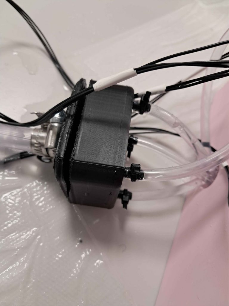
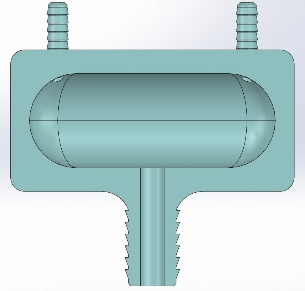
From the mechanical side, some issues with the hydraulic system appeared. Firstly we had trouble with keeping the input manifold from leaking. During the previous tests, it did the job, but was leaking like crazy. We decided to redesign it as a way to mitigate this. We did this in three ways. Firstly, changed from PLA to PETG, as it has better layer adhesion and is generally better in water. Secondly, we increased the infill to 100%, to prevent leakage through the print. Lastly, we slightly increased the diameter on the hosebarb, to prevent leakage between the manifold and the tube. We felt confident that these changes would keep it sealed. Our confidence was however shattered when the manifold exploded during use. We realized that the crack formed where there was a 90 degree angle inside the chamber, so we added large fillets to hopefully mitigate this. That has ended up working so far, and has as of 4 days later not needed to be changed.
Other problems from the mechanical side had to do with the cylinders. While trying to control the system automatically, it was clear that the movement was way too abrupt. In order to have controlled movement of the arm, the speed of the cylinder movement needed to be reduced. We did this by reducing the voltage to the pump from 12V to 10V, which limited the motor speed, and in turn reducing the flowrate. We also realized that the pump had an option to limit the pressure. This was helpful, because we could make sure that the cylinders don’t explode from being under too high pressure. With these changes, the control of the arm was much smoother, but the reduced pressure led to the bottom cylinder not being able to retract. This is the cylinder that is under the most tension, and retracting it means lifting the whole arm. We ended up going with a quick fix, by adding elastic bands to help rotate the joint. This seemed to do the trick.
After a wet couple of days of integration hell, the system finally started showing signs of working. Although it has not drawn an image, it’s clear that we are in fact successfully controlling a hydraulic operated arm. We had managed to demonstrate it moving with manual input through a Python script on a laptop. We will let the videos speak for the results:
With manual input working, many of our requirements were verified complete. The final one is to connect the Web UI, and running automatic jobs. As of writing, our system is not quite stable to run through large sequences of commands (300+). However, it does work for small batches, as seen in the video below.
That’s all for now!👋