Sondre:
This week I worked together with Theo to connect our two main parts of the robot system. Theo has been working on the A* pathfinding code that figures out the route through the maze, while I’ve focused on the movement side, making the robot drive straight, turn correctly, and fix its heading using the IMU. Our goal was to combine these two parts so the robot could both plan a path and actually follow it.
After a lot of testing, debugging, and trial and error, we finally managed to merge our code. The robot now uses Theo’s A* algorithm to decide where to go, and my movement code to drive to each cell in the maze. It took quite a bit of back-and-forth to get everything to run, but in the end we got both systems working together pretty well.
One challenge was that the robot wasn’t always facing exactly the right direction after turning, so I added the PID controller correction to make it drive a bit straighter. But fine adjusting the values proved to be a little pain, since one small adjustment made it not work, and then work.
Now that the main parts are connected, the next step is to clean up the code, make it more robust, and start adding the arm pickup system so the robot can actually grab the box. We didn’t finish everything this week, but we’re in a good position to finish next week.
Théo :
This week, I started by fixing an issue that caused my code and the car to not work consistently. The problem was that sometimes the path-resolution calculation ran too quickly and triggered the navigation before the motor and sensor connections were fully initialized.
For the rest of the week, Sondre and I focused on improving the accuracy of the movements. I mainly worked on optimizing the rotation values and adjusting the speeds of the different motors for the different moves. At the end we got it working pretty well, now it’s going till the end. It still needs a bit more precision so we’ll be able to add the pick up at the end.
Robin
The fabrication of the charger is more complex than anticipated. Although I had previously decided to design a charger with a 13V input, sourcing that specific voltage proved too difficult. Consequently, I have decided to switch to a system that steps up voltage from 5V to 13V. I located a schematic online featuring the CN3303 as the core component.
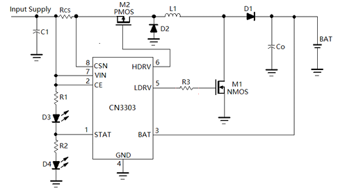
My goal is to reproduce this circuit and design a PCB, but I am currently encountering difficulties regarding the calculation of the component values.
Anette:
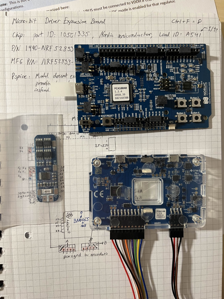
This week I talked to Steven about not being able to finish and order the PCB in time. This is mainly due to the limited time me and Robin had to make it, and the complexity of the microcontroller. Since I am also unable to simulate the PCB in Kicad spice simulation due to still not having any preexisting spice files for the nrf52833 chip, Steven let me borrow a similar board and a power profiler kit so I will be able to simulate it physically. I was going to do it over the weekend, but I ended up using this time trying to figure out an issue we had with the power.
Until now we have been using a powerbank as our main power source, but the plan has been to change this out with a battery pack using 3 xstar 3.6V lipo batteries. This is also where the bms comes in. We were going to get the batteries a while ago, but due to some issues receiving them I had to express order some from elefun on saturday. The plan is then to make a battery pack if the batteries arrive on time with the help of Øyvind from group 7. Since the custom BMS doesn’t have enough time to arrive either, the battery pack will use a preexisting BMS from Robin.
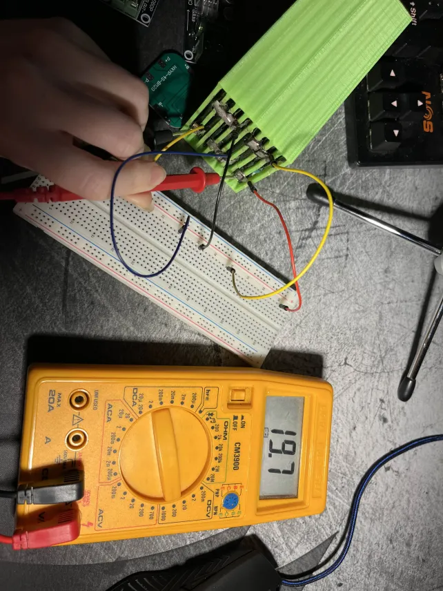
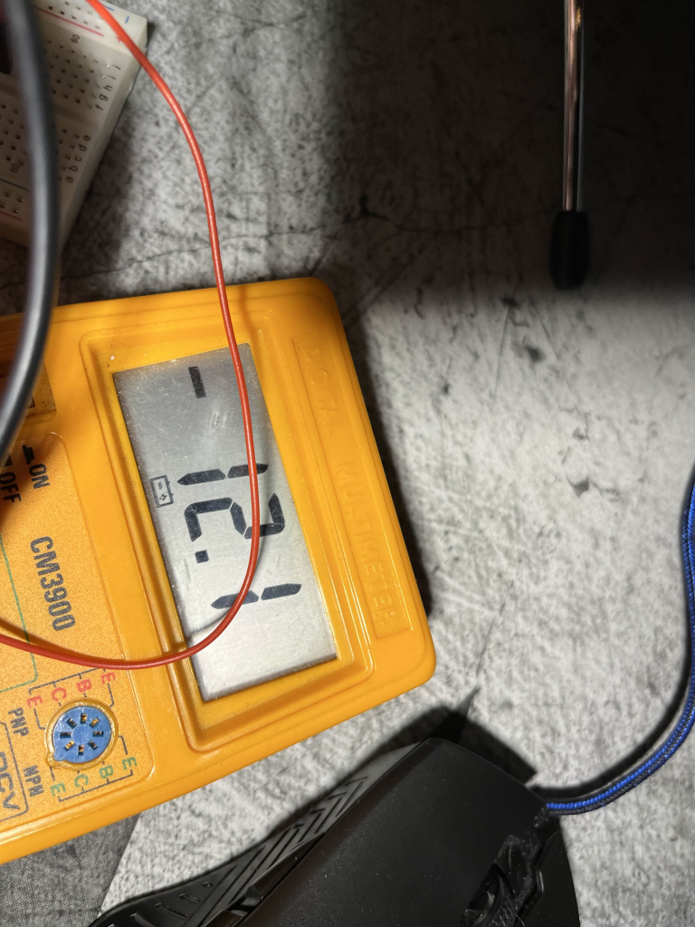
Before this was decided I ended up finding a backup solution for the power with the help of Daniels from SmartSystems 2023. He let me borrow a lipo battery, a bms (HXYP-4S-BM20) and a buck converter (CR-D4080P). The battery is too big to attach to the car, but it would bring a more consistent power source than the powerbank and could be carried on the side so it wouldn’t be in the way. I then ended up testing the different components to check the values. The battery itself was 19.7V and made up of 4 cells with 5 ish V each.
I then tested the BMS which was difficult since I don’t own any clamps and it was hard to make sure the cables stayed in place. The setup therefore ended up looking a bit questionable, but it worked and showed the BMS gave us an output of 12 V.
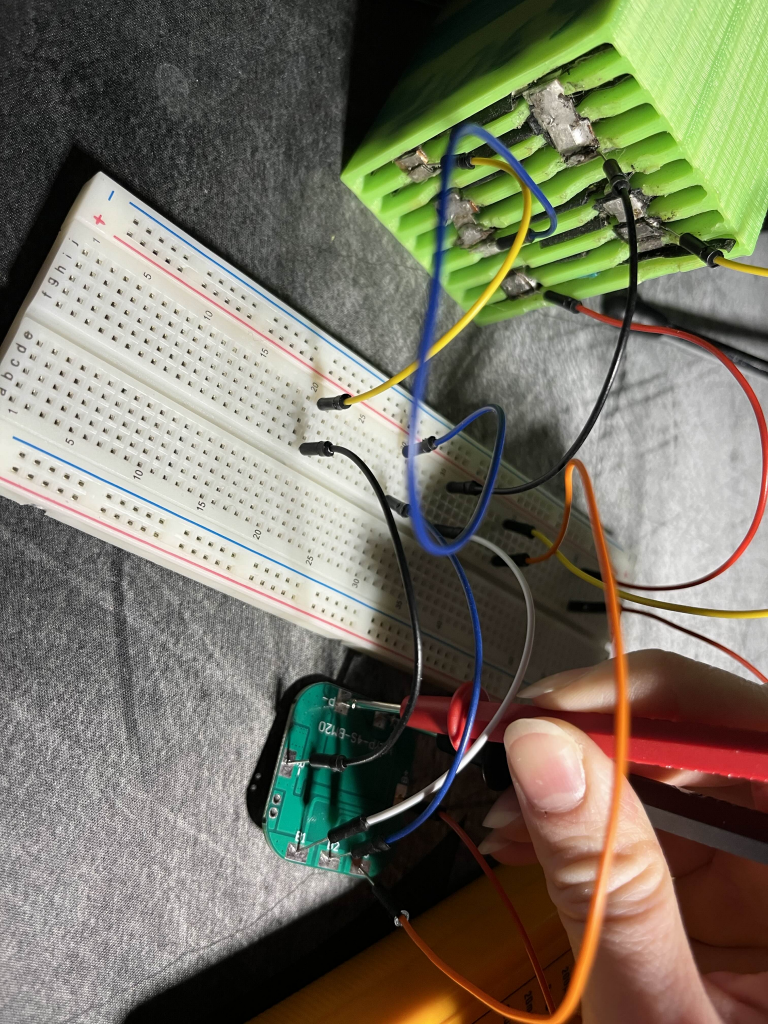
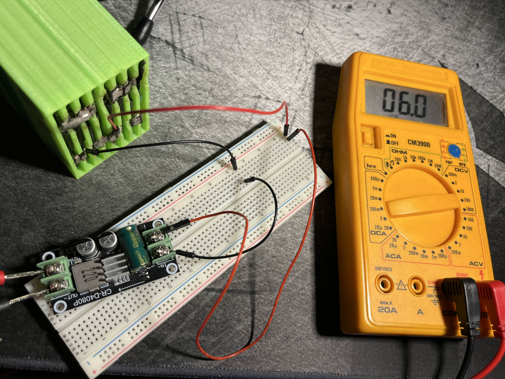
Furthermore I tested the buck converters. I didn’t want to struggle with the BMS setup again, so I tested it with 2 of the batteries (10V, the input voltage range is 7-38V). This then gave me 6V even tho the datasheet said it should be 5?
I also got a tip from Steven to compile the stuff I have done that’s missing from the blogpost in a pdf file and add to the blog, so I have started compiling a document of my work that I will post next week. This will then also contain the missing PCB schematics and documentation that I didn’t want to post because they looked too messy.
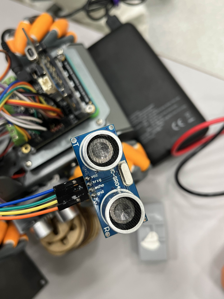
Lastly this monday me and Robin tried to solve an issue with the SR04 for Sondre and Theo. The side sensors kept occasionally malfunctioning. We tried to measure the connections and the power consumption and compare this to the datasheet to see if we could find the problem, but they seemed to be correct. We also checked the pins to see if that might be part of the issue, but we didn’t find anything wrong with the sensors. Also the front sensor never got damaged, only the sides. We ended up not finding any issues that could break them consistently, except if they broke due to them falling of the car because the 3d printed parts that are attached to the car keeps falling off. We also had a theory it might be due to us not having enough power for all the components during the spike of the wheel motors? but if that is the case this will hopefully be solved when we get the battery pack.
During the meeting on monday we (Sondre, Theo, Robin and me) also talked about what to write for the last blog post next week and what we should do before then. We also looked at the email about the oral exam and what we need to do before this.
Matias:
This week I tested the step-down regulator to confirm that it works correctly with our battery voltage of 10.8 V.
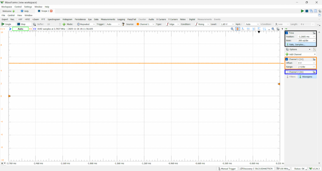
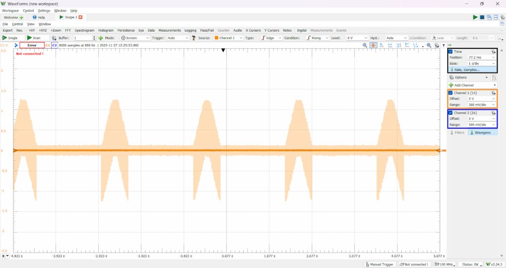
I also worked with Sondre to test the different active filter configurations. He helped me set up the code for generating the PWM test signals, and together we analyzed the output using the Analog Discovery.
This one is without filter, we can se how the entry is more “spiky”
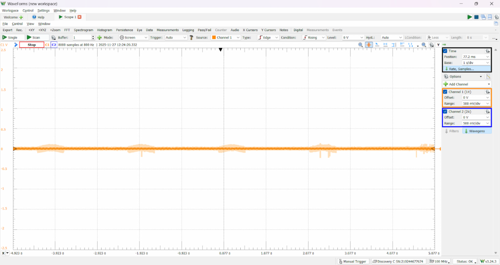
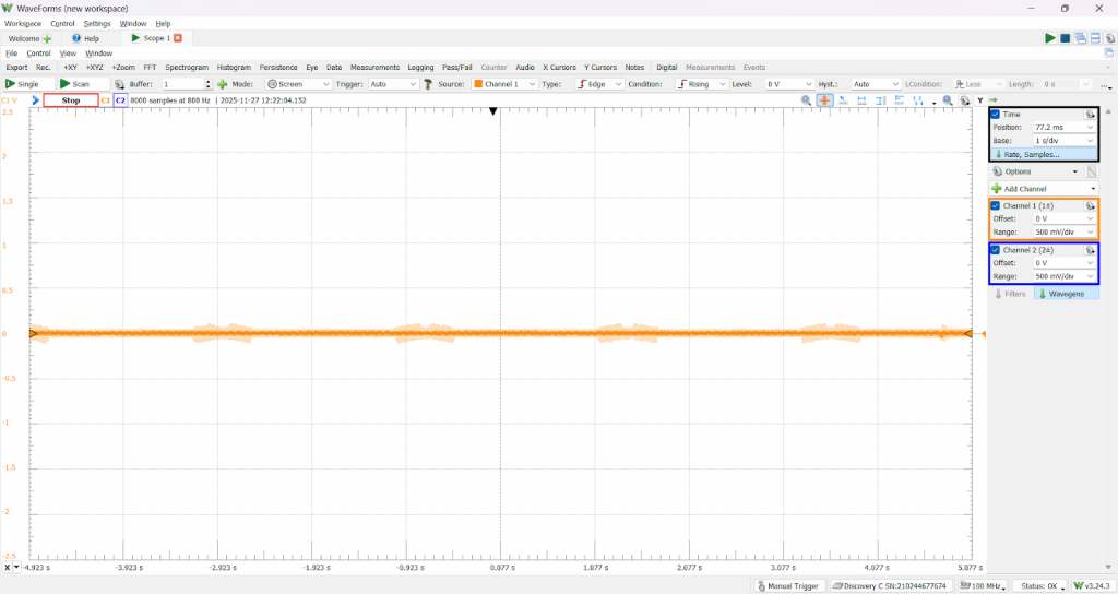

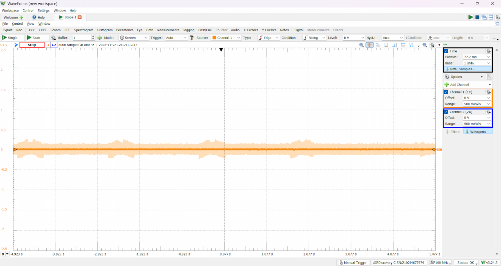
Based on the measurements, we decided to use a strong filter, since it provides smoother and more continuous movement — and because our application doesn’t require high speed, this configuration fits perfectly.With these decisions made, I’m now getting to work on finishing the prototype, integrating everything on the protoboard and preparing the system for the next round of testing.