Wang
This week I have been mostly focused on doing decent game development since we had the last inleveing this Thursday. But I worked with smart systems on Friday before I start practicing for santid systems. I have now set up that they will constantly search for verandre to di finer verandre, but when they have been connected the data from the joysick will not be sent over anymore until I hold down button A. So the plan with that is that I don’t want to control the car constantly so I have created a function that I call idel where it will go off by itself I have only done this with led here. But then when I hold down button A I will be able to send signals from the joysick again and then the receiver will go out of idel and into joysick controls like before. I haven’t put it on git yet but I will.
oid led_start_idle_animation(void)
{
    if (idle_running) {
        return;
    }

    printk("Starting idle\\n");
    idle_running = true;
    idle_step = 0;


    k_work_reschedule(&idle_work, K_NO_WAIT);
}

void led_stop_idle_animation(void)
{
    if (!idle_running) {
        return;
    }

    printk("Stopping idle\\n");
    idle_running = false;

    k_work_cancel_delayable(&idle_work);
    led_all_off();
}
Week 16:
Not too many updates since last time, I’ve been busy with exams like ‘Santid’ (Real-time systems/programming) and ‘Mathematics 2,’ but I have now tried to make the car more responsive. I have a problem where if I move the joystick too quickly, it stops a little, and it won’t drive backward anymore until I drive forward a little. However, when I have the cable to the micro:bit plugged in, it responds quickly again.
We still have time, so now the focus will be on fixing this, fine-tuning, and putting it together with the other parts. I have now only included the libraries Oskaras created for motor_controls and pwm.
The main thing I have changed today is that I have separated the joystick functionality from motor_control. I originally had it inside there.
Link for git:
WangKKing3/Bit_Player_micro_bit
Merge pull request #1 from WangKKing3/car-movment · WangKKing3/Bit_Player_micro_bit@c4e8bfb
opptate · WangKKing3/reciver@15901c0
Oskaras
15:
This week i didn’t get almost any progress done. I had the Game Development course game due for this week. Which i was busy with for the entire week of 8+ hours each day.
16:
This week from the start of the week i prepared for the Ada Oral exam. Being the first Oral exam in this university that i have attended. i focused solely on it not having a lot of progress done at the start of the week until Thursday. Afterwards i made a serial communication chat in zephyr. This will be used for taking commands from the raspberry pi or in worst case show that it is possible for the car to take commands via serial and act upon them. So if i get a message Forward from serial the car will drive forward and so on. it can now send data forward and receive it as well at the same time with no restrictions.
Code for the serial chat: https://github.com/OskeLTU/i2c_reciver
code video:
note that it’s called i2c_reciver. That is only because i started to implement i2c, but found that serial was easier and accomplished my goals anyway. The way it works is that i both receives and sends data through the TX and RX ports. We have also tested it with The raspberry pi one the fundamental level. still needs some refinement
We finally got the serial communication to translate from the microbit to the pi here is the showing of that
raspberry pi example:
And so it will run as the autonomous part of the car taking commands and processing them. while we also have a manual override with another micro bit using Bluetooth. we have gotten the car to run mildly using the joystick. It interrupts the main while giving instructions using the car and the main resumes right after the controller doesn’t give more instructions.
Code for the current main code: https://github.com/OskeLTU/Zephyr_code/tree/working
this is the current code base for the car. I will implement the serial files into here in the same manner with a library as the pwm and motor controls. And will add additional integration for reading the serial messages and furthering them to the motors.
The Bluetooth for the receiver in wangs code will also be added on in the same project. This will come this week, we are almost done with it as well.
Henning
Week 15:
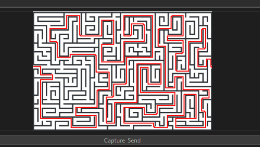
So for week 15 it was kind of a slow week on my part! Reason being other exams taking priority and full focus. But I did manage to get a few hours in and finally I was able to fix the drawing problem I had for weeks now. Here is a demonstration of an image which I will describe:
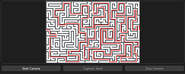
As you can see it can fully draw mazes even if they are more complex. Now this code has a flaw, but it is the best I could do for now. If the image isn’t scaled and there would be white spaces around the maze, it would not be able to find the entrance/exit and rather give me an error that it can’t draw the maze. So, it has to be perfectly scaled around the maze to draw anything. This could be an easy fix, and I will try and find a better solution towards the final presentation. But I am happy to see that I can finally see my code draw the mazes correctly.
Now another flaw with this system that I talked about with one of my mates in the group. There are two different engines running here. So what solves the maze is a BFS:
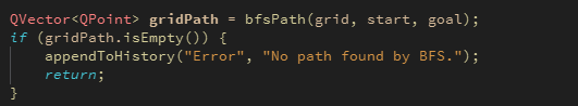
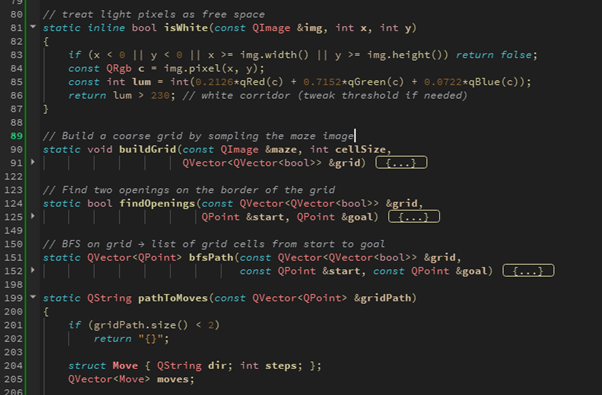
I had to add a lot of helpers in the top of my code, each one being specific restrictions for the drawing method. Now why this is a problem which I previously mentioned by being two separate engines is that the BFS (drawing tool), it does not communicate with the AI, so I can`t get directions through the maze which I want the AI to produce to the car. I will be looking at that through week 16.
Week 16
This week was a big win on my end. Now I have been able to add a communicator between the BFS and the AI. This way I can have the AI communicate directions through the maze that has been drawn. Which should also be easily connected to the PI and the car code.
Here is a demonstration:
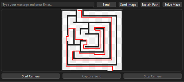
- BFS draws the maze
- I added a new button “Explain Path”
- This sends a prompt of the BFS drawing which then asks for directions to the AI
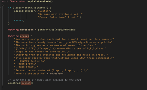
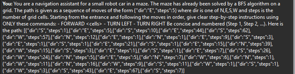
Previous image shows the prompt that’s being sent. As you can see the picture gives us the direction in N(north), W(west), E(east), S(south), and gives the steps of each cell. The cells being the core of how the PI can easily be setup with these cell steps.
The AI will also reply with each step. So, it looks like it comes out twice, but originally the AI is converting the N, W, E, S into programmable language:
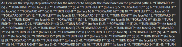
The AI gives a very detailed description of how the car should drive to traverse the maze in the fastest way possible.
I am very happy with my result of how the AI has been built throughout this project. Now, I fear the merging of the AI and the other components like the PI and the Car, but I will stay positive and do my part so its implemented in the best way to our final presentation on 19th of December.
As a bonus to show you all. The AI works with all the mazes, even the bigger and more advanced ones:

The text is sadly extremely small in the pictures, but it gives the directions even through the bigger more advanced mazes. So, I will by that say that I have the AI up and running. As this is the last day of our blog post, I want to add that towards the final day of this project, I will be focusing on polishing the code. See if I can make it even better for overall mazes and directions. Make the merging of the AI –> PI & car go smoothly and document all my code and work which makes it more understandable.
What i`ve achieved through this project and which im happy with:
I have made an AI which we can communicate with.
I can capture images through the AI where it can describe environments.
I have an engine which can draw mazes which can be further improved for mazes.
I have coded a communicator between the engine and AI so they can now communicate with each other and send directions.
And i have implemented a memory for the AI so it can recall our previous discussions and further help us traverse mazes and further descriptions.
Zardasht
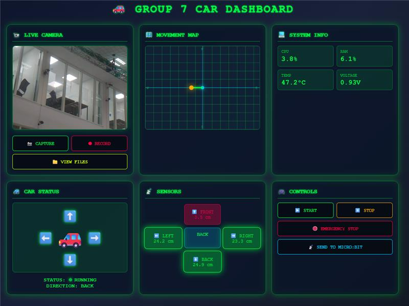
Upgrading My Smart Car Dashboard: A Cleaner, Smarter Interface
As part of my ongoing smart car project, I recently redesigned the dashboard interface to improve clarity and functionality. One major change was removing the sensor value plot, which I found visually cluttered and not essential for real-time monitoring. Instead, I added a clean visual of the car alongside a dynamic movement map that tracks its direction and position more intuitively.
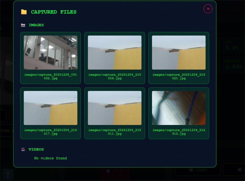
To enhance usability, I implemented a live camera feed with options to capture images and record video directly from the dashboard. These files are stored and viewable in a dedicated gallery section. I also introduced a compact sensor box that displays distance readings from all directions—front, back, left, and right—making it easier to assess surroundings at a glance.
System performance metrics like RAM usage, CPU load, temperature, and voltage are now shown in a small info box for quick diagnostics. Additionally, I added a button to send all relevant data to the micro:bit via serial communication. While the serial function is ready, I haven’t had time to test it due to exam preparations.
Overall, this update makes the dashboard more professional, minimalist, and practical—aligned with my goal of building a reliable, real-world interface.
Øivind
Last week’s blogpost in Development of Smart System
Not too much to write about, only decent work regarding the course was helping another group. I learned from helping also and that’s nice. With an exam on Monday, Wednesday and a report for a week’s worth of work on top of helping the other group, and as always when you start something, something unexpected happens and time flies. This is hard facts, no excuses.
It has been the hardest week yet since I started USN. While I write this, I’m glad I can focus and fully indulge in our Moon-Rover until after the presentation.
I have done a bit of research on the vacuum-pump and hose I will implement. I miss documentation on the motor and hope I do not run into critical problems.
As instructed, I will get wiring schemes, CAD drawings for wire setup and body of the car either resurrected or make new ones to deliver on the USB stick after the final presentation.
But you deserve at least a picture of something. A video is out of the question since the report only allowed sleep between 0330 to 0600.
I foresee that when we get near deadline, we will be taught yet a lesson on last minutes work. But I feel we are pretty solid after each member has hold strong onto dedicated task through the semester and we are all highly motivated to use all of the time awake getting the rover as intended and functionable for the tasks we have decided it will execute.
I am open to critique on my choice of components. Some things might be overengineered; others could be better. When ordering parts I realize I should have checked I ordered the right types, not like with the transient diodes, where I got surface mount types, not through-hole as intended.
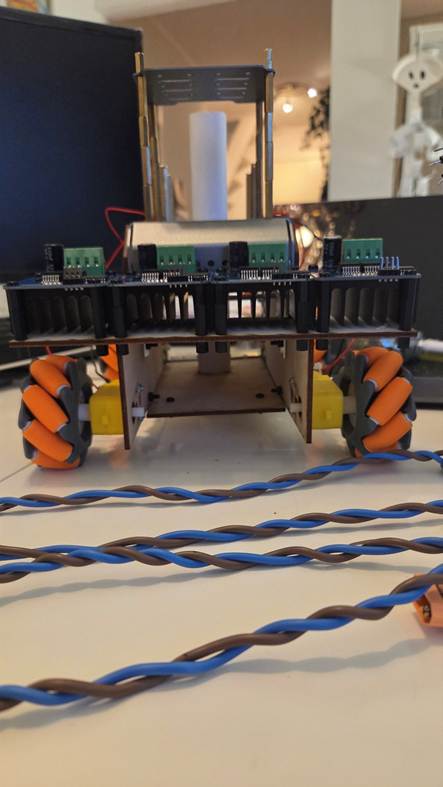
Pictures as promised, thou not very serious. I hope I can surprise you on the presentation with features I might have forgotten writing about in the blog.
The pictures show that I have some soldering to do!
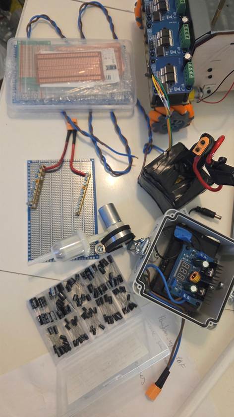
See you all!
-Øivind