Sander & August Presents:
THE ASTROROVER PROJECT
https://github.com/augustkode/TheAstroroverProject

Abstract
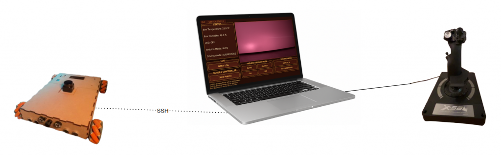
This final blog sums up Sanders and Augusts work. The theme of this project is space. The task was wide, and provided us significant freedom of exploration and opportunities to grow within systems and computer engineering. From here we derived the problem domain and ultimate goal: safe autonomous data collection. To achieve this, we have used sensorics and actuators. Some of the sensors used are LiDAR, DHT11, Ultrasonic sesnsors, IMU and barometer. Some of the actuators used are mechanic wheels. The methods followed was kanban, agile scrum and UML. We achieved our ultimate goal of autonomous data collection. The data is displayed in a GUI, and the results are logged in a file. We collect data, both from the environment and from the system.
Preface
We would like to thank Steven Bos and Richard Thue for great help and guidance. We also want to thank Henning Gundersen for great music.
Demo Video
Table of Contents
- Problem Domain
- System Requirements
- System Design
- Challenges
- Improvements
- Conclusion
Problem Domain
The problem domain of our project are safe autonomous data collection. We are of course not on mars, so our concerns lies in how to make the car autonomous, how to gather sensor data and how to display the sensor data.
Our greatest challenge have been merging every working and verified sub-system, and make them collaborate in real-time.
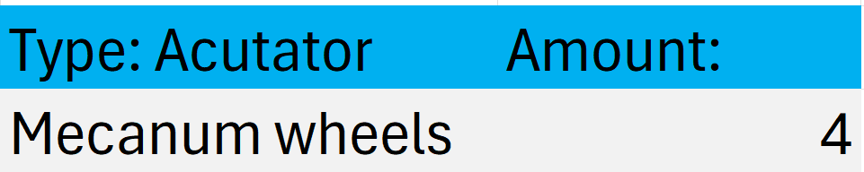
Our starting point was a pre built schaled down electric car, with mechanum wheels. The challenges and concerns raised was:
- How could we make the car drive fully autonomous?
- What data should we collect?
- How could we gather data?
- How could we mount the sensors?
- How could we display the data?
- How could we control the car incase of an emergency?
- How could we see where to drive?
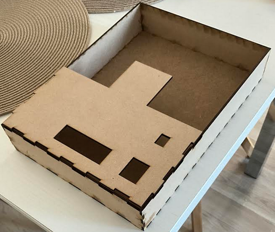
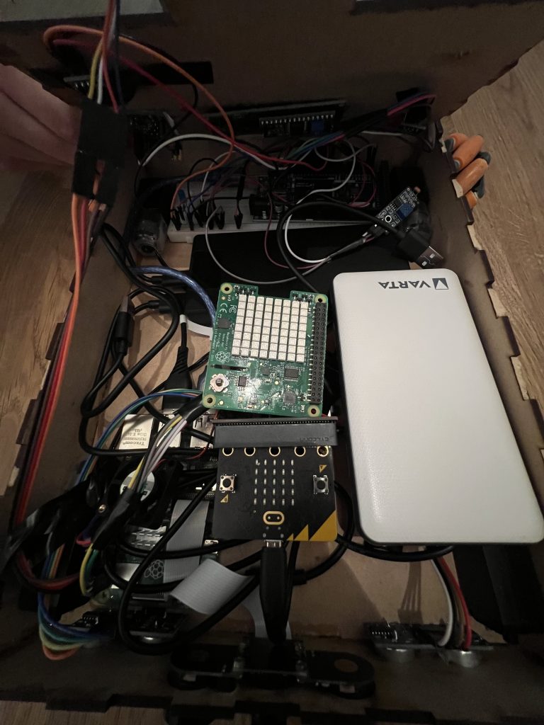
- How to fit and place all the components within a small frame?
- How can we map the environment?
- How to fit everything?
Tools
We have held one group meeting a week, where we have talked about progress. We have used kanban and agile scrum. Most of the work have been done at home.
Development Tools:
- tree.aiga
- Github
- ROS2 humble
- Ubuntu 22.04
- Ubuntu 22.04 Server (RPI)
- VSCode (with remote SSH)
- RViz 2
- Gazebo
- DrawIO
- Qt
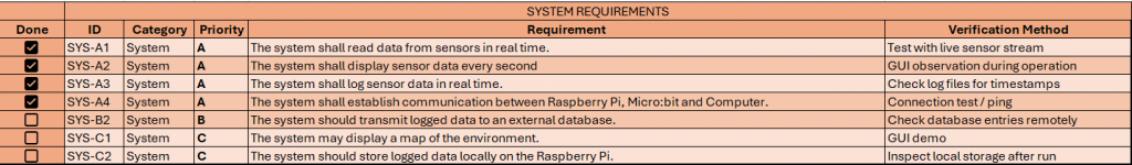
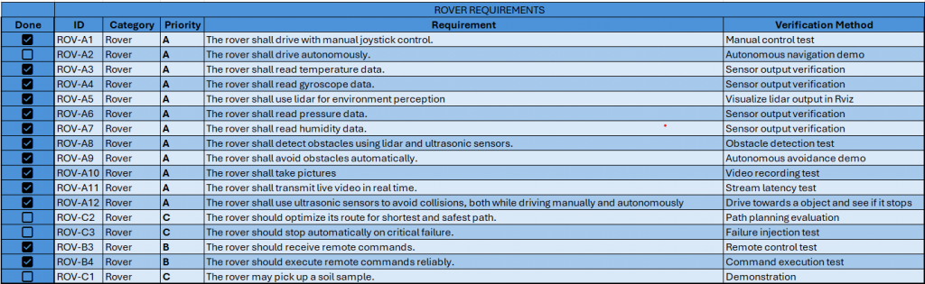
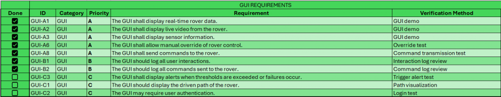
System Requirements
We split the system into three requirement categories:
- System requirements
- Rover requirements
- GUI requirements
System Design
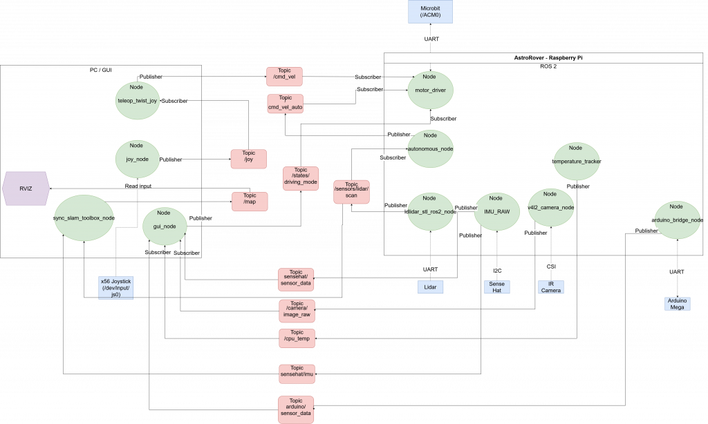
ROS2 Diagram
Features
Raspberry PI 4B
Runs:
- Lidar_node (stl lidar node, provides lidar input to /scan)
- Autonomous_node (Autonomous driving and lidar processing, using lidar data)
- motor_driver node (Parsing driving commands to micro:bit from cmd_vel and cmd_vel_auto)
- Arduino_bridge_node (Provides functionality. DHT11, LCD, PIR, RGB, Photoresistor)
- temperature_tracker node (Provides PI CPU temperature)
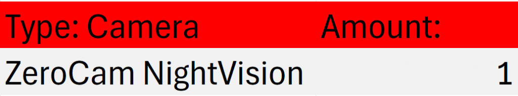
- camera_node (provides camera stream from ZeroCam NightVision)
- sensehat_node (Privides IMU data, barometer, and car internal temperature)
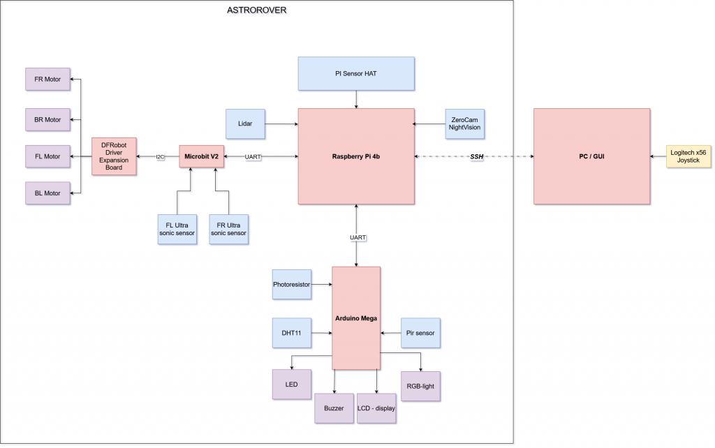
Micro:Bit V2
Runs:
- Parses driving commands from motor_driver mode to run motors.
- Ultrasonic sensors (Emergency stop, separate from ROS 2, to protect camera in front in case of user error or autonomous malfunction)
- Motor Driver Board (Controls motors)
Arduino Mega 2560
Runs:
- DHT11
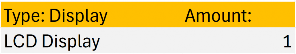
- LCD display
- Photoresistor
- PIR sensor
- RGB light
- Buzzer
PC
Runs:
- GUI node (displays live camera feed, system status and other sensor information)
- Teleop_twist node (Processes /joy data and publishes on /cmd_vel)
- Joy_node (Handles joystick input and publishes to /joy)
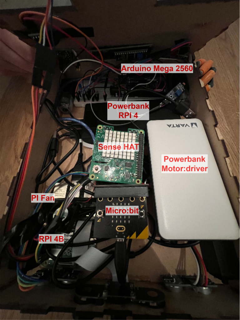
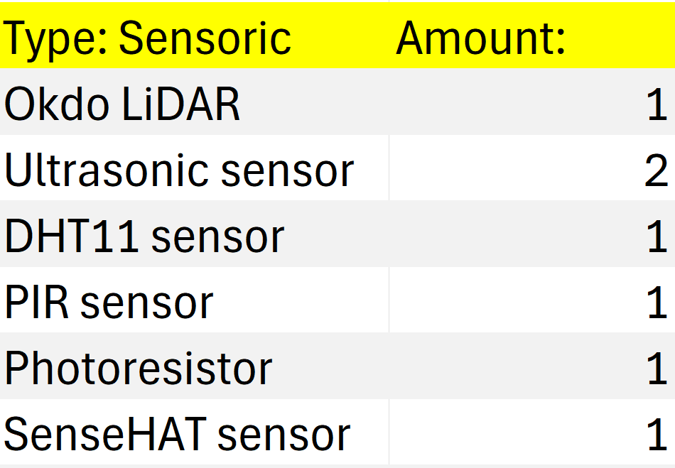
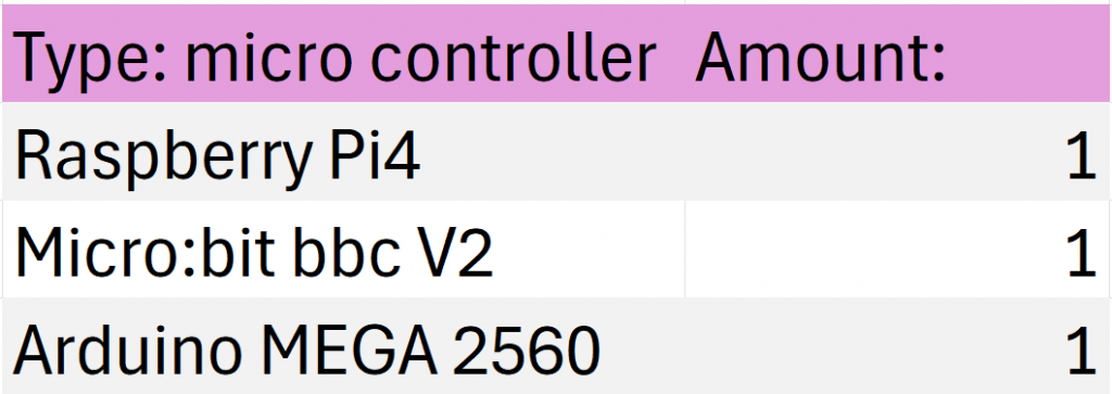
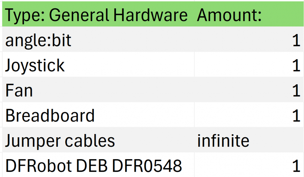
Component List

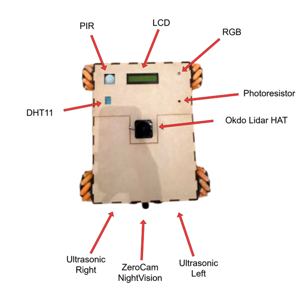
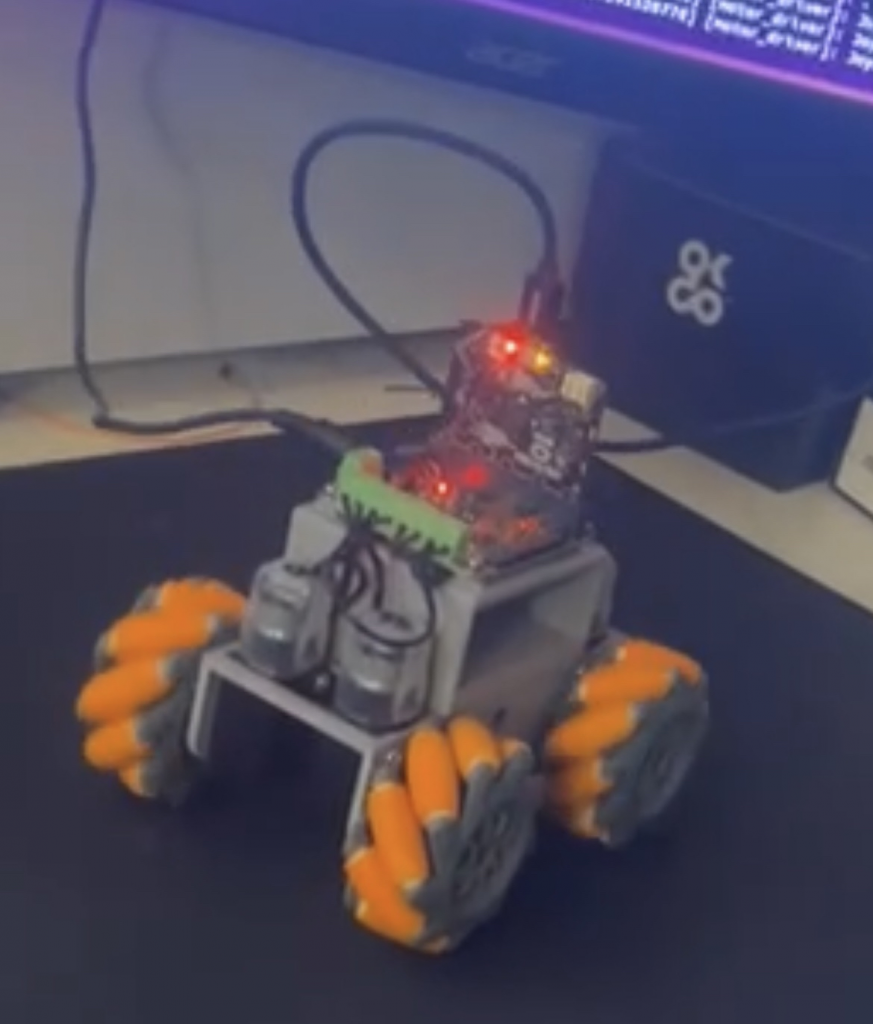
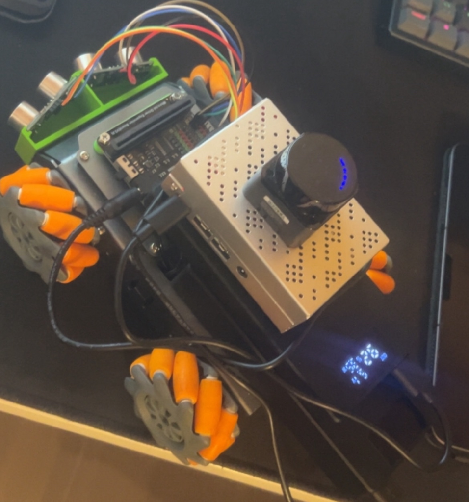
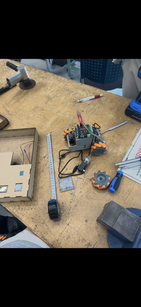
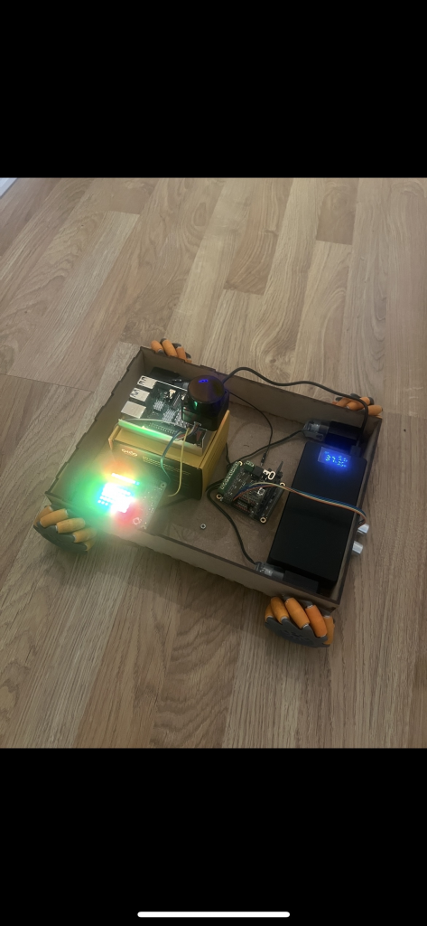
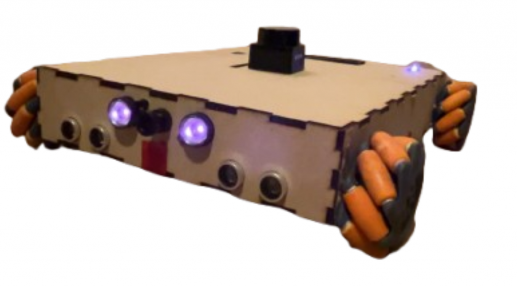
Car Design

Evolution of the ASTROROVER


Challenges
We have met two great challenge, that we have yet to defeat. We have not been able to make mapping possible with IMU data, and we are experiencing intermittent faults in our arduino sub-system.
We get LiDAR visualization in Rviz, and we can somehow measure and display the room. But we have not been able to integrate the IMU data with the LiDAR.
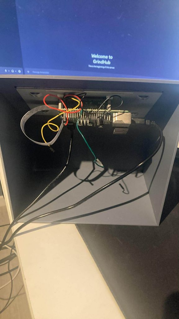
The intermittent faults we are experiencing comes and goes. Most of the time, the lcd display and DHT11 sensor works. These are the most important components from the arduino, so this is fine. We have tried to solve the problem by removing every unessecary jumer cable, but this didnt solve the problem.
Improvements
If we where to do this again, we would have used wheel encoders to get odometri combined with LiDAR for more accurate mapping. We would also buy a powerbank without PD. These have to much constraints, and wouldnt drive the motor board. We would also used kanban on Github instead of tree.aiga, because everything would have been on the same site.
Conclusion
We achieved our ultimate goal, safe autonomous data collection. The system is also able to map the environment to a certain degree, check improvements for more information. The GUI, the joystick, and the vehicle are tightly interconnected. All three subsystems are essential for the overall system, and each one must function properly for the others to carry out their tasks.
Final words
We want to thank you for a great course! When we started out we felt kind of overwhelmed. We had a vision of what we wanted to do, but we where not sure how to do it. Now we know. The experience gained from this course can not be described. In january, when we are starting up writing our bachelor, we will continue on with Qt, VSCode and ROS2 on Ubuntu. The amount of hours we will save in january, already spent the hours on how this semester, is amazing.
Software might not solve every problem, but hours spent will.
This have been truly inspiring. We have genuinly matured as future engineers. Again, thank you!
– August & Sander.
Sanders & Augusts work for week 14 &15
The last two weeks have been absolutely crazy. We have finished up our exams, while we have been deep diving into making the car fully autonomous. Talk about concurrency! Our uniprocessor, brain, have been running for a time on fixed priority scheduling. For the whole semester, we have had a fixed task set with the same period. Every task have had the highest priority, but still bound blocking was no problem. The lest weeks we also had a somwhat earliest deadline first, and we have delivered correct output within the time constraints in every subject. What a ride this have been. Speaking of ride, lets talk about the work to get our rover fully autonomous!
Arduino:
The terms from real-time system keeps on rolling. We have been experiencing intermittant faults within our system. Scoping in, it is located on the arduino and its sensors and actuators. When running the arduino node and the gui node, sometimes there would be no sensor reading beeing displayed in the gui. When debugging we runed: ros2 topic info /arduino_bridge, and it said that one node was publishing on this topic, and one was subscribing from this topic. This meant that all was fine, regarding the logic of running the nodes.
We opened up the whole thing, and started by removing every unnessery connected (skjøtet) jumper cable, hoping this would sold the problem. It helped to a certain degree.
Working:
DHT11 -readings
Status showing in the LCD-display
PIR-sensor
Not working:
Led pins
RGB pin
Photoresistor
We have spent a lot of time debugging this. Sometimes the rgb works, sometimes it does not. Our most important features in the arduino works, so we are closing this case, at least for now.
Fully Autonomous Rover:
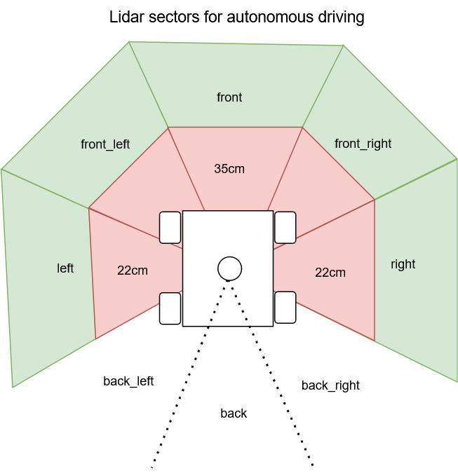
The LiDAR code from an earlier week, was used in the newly made autonomous_node. The LiDAR code from earlier was split up in 7 different sectios, corelating to the 7-axis movement of the car. The LiDAR code filters invalid measurements, and finds the minimum distance in each sector. Since the motor_driver_node used /cmd_vel we planned to have the autonomous node publish on to this topic, from the decisions made with the measurements from the LiDAR. We used our experience gained from intelligent real-time systems, but this time with a much more sophisticated sensor. Since we had split up the LiDAR in 7 seven sectors, we used the same logic. Check picture for what sectors being used in this project.
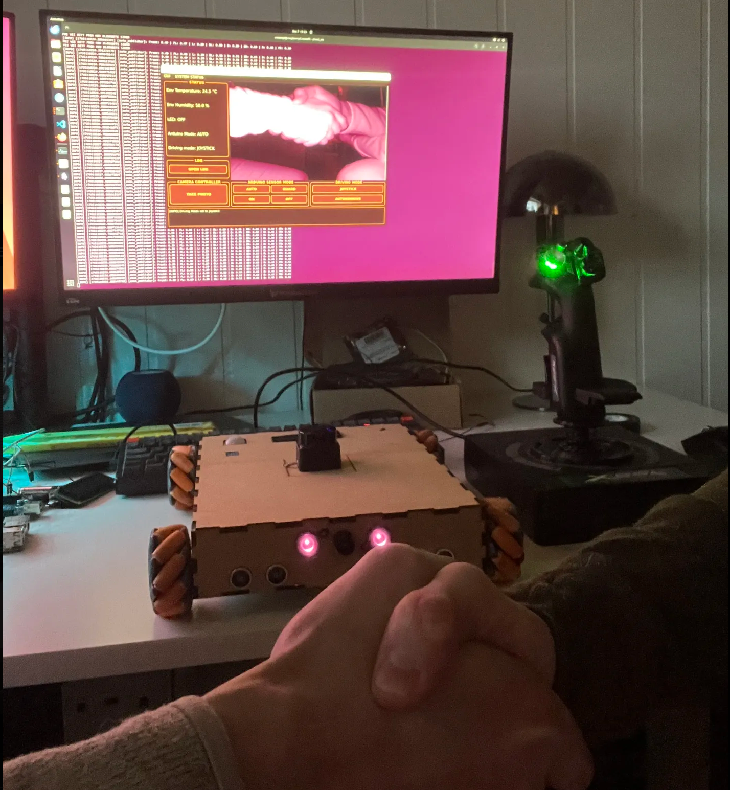
sWITCHING BETWEEN MANUAL AND AUTONOMOUS DRIVING
For some weeks ago we made placeholders in the gui for switching between autonomous and manual driving. This was a the /driving_mode topic. The gui publishes a string on the topic (“joystick” or “autonomous”). We had the motor driver node subscribing on this topic. We figured autonomous node had to publish on a different cmd_vel, so we created cmd_vel_auto. This was to simplify the switching between the joystick and autonomous. This separated the two input methods. In the motor driver node, the driving mode topic is used to differentiate wich of the cmd_vel to use for what driving mode, and forwarding what commands being sent to the micro:bit.
Sander & August out.
Sondre: Final Digging before Hard deadline
Final kjøh
Camera Package
I started the week by implementing the camera package (a ROS2 package) that will simulate the rover’s camera. This allows me to test the camera window and the snapshot function that I will also implement. The package functions as its own ROS2 node, which the dashboard package can subscribe to in order to receive a live feed.
The camera package is implemented in Python because it provides the best support for OpenCV and camera handling. It also makes it easier to read video frames and convert them into ROS messages.
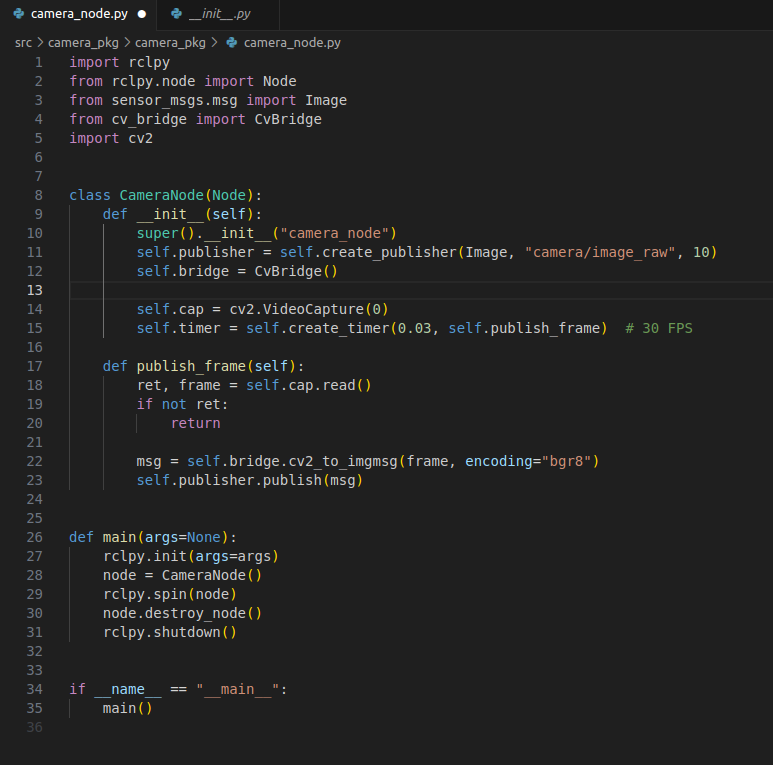
camera_node.py
Here we have the code that implements the camera node. We import “rclpy” and “Node,” which give us ROS2 functionality. OpenCV is a library that makes it easier to process and analyze images and video, and here it is used to read frames from the camera. cv_bridge is used to convert OpenCV images into ROS2 messages. These libraries give me everything I need for the camera to work with the ROS system.
CameraNode is the actual ROS2 node.
Inside the class, we have two functions called init() and publish_frame():
init():
- calls super() which sets up the ROS2 functionality and gives the node the name “camera_node”
- creates a publisher that publishes images to the topic “camera/image_raw”
- initializes CvBridge(), which is used to convert OpenCV images into ROS messages
- opens the camera and sets the framerate
publish_frame():
- reads an image from the camera using cap.read()
- converts the image into ROS format
- publishes the ROS messages (the camera feed) to the topic, which the dashboard can subscribe to
Implementation of the Camera Window and Feed
The next step was to create a dedicated window to display the camera feed. Since this was only a layout task, it was a quick job. By adding a separate Image box in main.qml, where the QML code for the dashboard is located, I created a properly sized window for the feed.
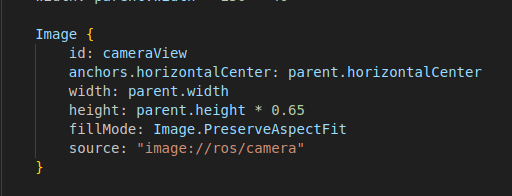
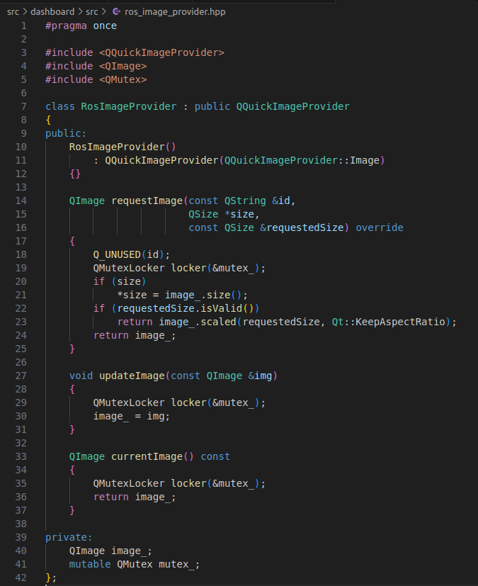
The feed itself comes through the source field, which points to “image://ros/camera”, which in turn receives the images from a RosImageProvider class defined in the code. This class receives updated images from the camera node and makes them available to QML. The class has two important functions:
updateImage(): This function receives the newest image from the camera node and stores it in the RosImageProvider so the dashboard can retrieve it.
currentImage(): This function returns the most recent image stored by updateImage(), and is therefore an easy way to create a snapshot function, which is described further down.
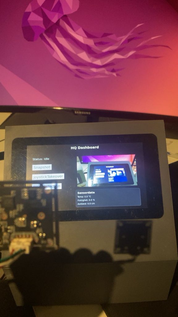
Result
Now we have two packages in the system that we can build and use: the dashboard and camera_pkg. The dashboard package starts our GUI (the dashboard), and camera_pkg starts the USB camera connected to the same Pi, which simulates the rover camera. When both are built and running, we get a dashboard that displays a live feed, as shown below.
Final Squeeze (Snapshot Function)
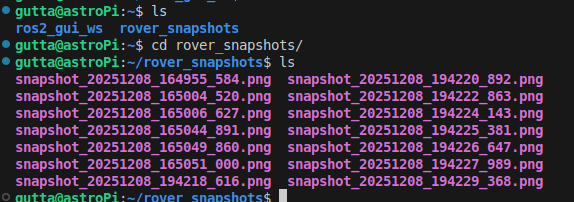
The last thing I did before being satisfied with the project was to add a snapshot function to the dashboard, which is a button that takes a snapshot of the camera feed and saves it in the “/rover_snapshots” folder.
This function simply needs access to the currentImage() function in RosImageProvider, because it returns the most recently stored image from the camera, and then we just save this to a separate folder. So when the Snapshot button is pressed on the dashboard, it calls a takeSnapshot() function in RosNode, which retrieves the latest image via currentImage() and saves it in the “/rover_snapshots” folder.
The image below shows stored snapshots in the folder.
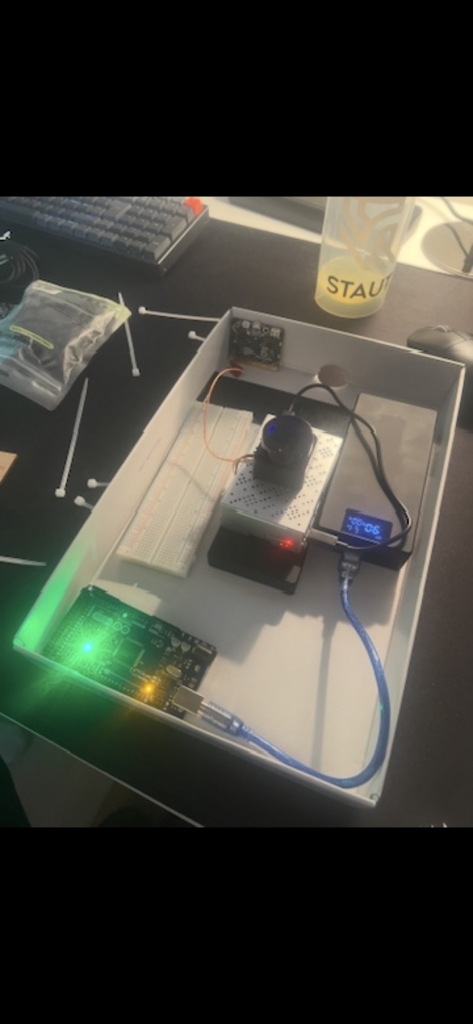
What we have
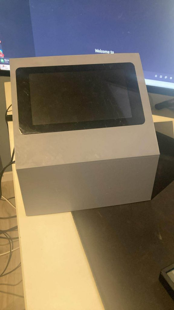
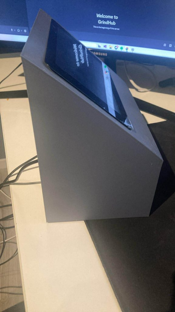
- A physical groundstation (A.K.A “bakkestasjon”)
- GUI/dashboard ready to connect to the Rover
- A working livefeed-Window to display some cool things
- A working panel that are ready to show sensordata from Rover
- A Working snapshot-function that saves images in a folder
- Some dummy buttons that have huge potential
What we dont have
- Time
Last Thougts
Since we started with the bakkestasjon so late, we didnt have time to make it a finnished product, which makes me sad. But if had more time i would have started to integrate it with the Rover, since many of the function of the “bakkestasjon” is ready.
Oliver
The GPS part of the project was not fully implemented. Due to illness and several other school projects, I managed to set up the code, but I was not able to get the integration working. Because of time constraints, I did not finish the reception, interpretation, and display of the positioning data.
AstroRover Bakkestasjon Final Results ( By Sondre and Oliver)
GithubLink: https://github.com/bjurve/bakkeStasjonRover
Pictures:
Block diagram
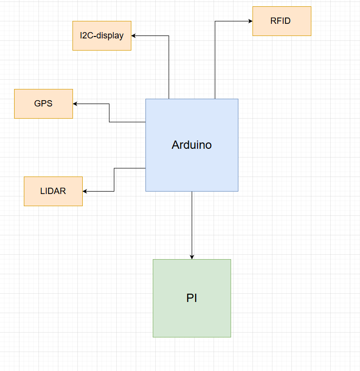
A block diagram shows the main components of the system and how they are connected at a high level. It provides a simple overview without detailed wiring or technical specifics.
Component List
- GPS Module (Swift Navigation Piksi)
- LiDAR
- RFID Reader
- LCD Display
- Arduino Mega 2560
- Raspberry Pi
- Raspberry Pi touchscreen
Demo:
AfterThought:
Remaining Tasks
- GPS integration not completed
- Arduino ↔ Raspberry Pi communication missing
- Connection to the rover not finished
We split the project into two main parts, but we did it too late. This made coordination difficult. Which made it difficult to find tasks to work on and contribute effectively. One member struggled with illness during the project, This caused delays and setbacks. As a result, several system components were left unfinished