Sondre:
This week I focused on improving the navigation and stability of our mecanum robot. One of the main problems earlier was that the robot often confused a wall with a box, since the ultrasonic sensors saw both situations almost the same way. To fix this, I added a simple verification step where the robot strafes slightly to the side and checks if the front distance changes. A box gives a large difference, while a wall barely changes at all.
I also spent time debugging the left ultrasonic sensor, which sometimes returned completely unrealistic values. This caused issues for the PID controller, especially in narrow corridors.
Another task this week was reorganizing the servo code for the robot arm. Theo originally wrote the arm logic, and I made it into a small PlatformIO library so we can control the arm cleanly from main using simple functions. This will make it easier to integrate the arm into the final system.
Most of my work went into improving how the robot behaves at intersections and after turns. I added logic so the robot fully stabilizes its heading before the PID controller takes over again, and added a short cooldown period to avoid fighting between the correction code and PID. I also added a small forward “escape” movement after every turn so the robot doesn’t re-detect the same intersection and spin back and forth. These changes made the movement much smoother and more predictable.
After talking with Steven, I also realized that I shouldn’t overcomplicate the system too early. I had added a lot of advanced logic, but some of it wasn’t fully finished and created more problems than it solved. So I took a few steps back and focused on making the basic functionality strong and reliable before adding more complexity.
Overall, it’s been a productive week, and after Monday I’ll be ready to continue progressing faster. Under is a video of how the robot moves now:
https://youtube.com/shorts/MFTijbGVwuM?feature=share
Robin:
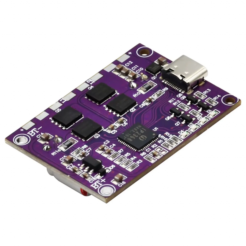
With the BMS (Battery Management System) successfully realized, the next step is to manufacture a component capable of charging the batteries.
1. Circuit Topology
*equation are wright in LaText because i write it first in Notion
To achieve this, I selected a schematic based on the CN3722 controller.
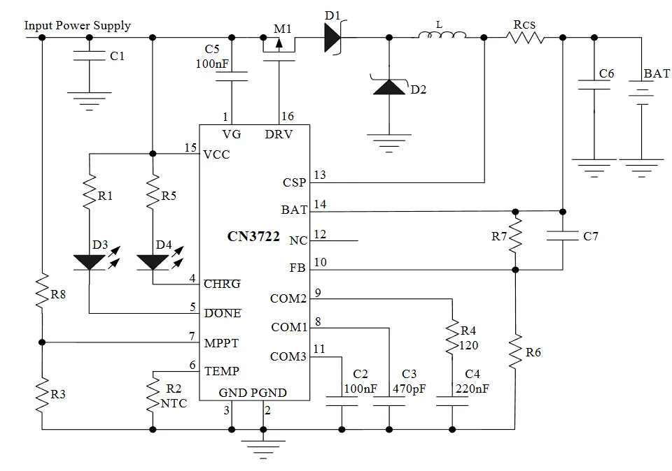
The component values must be adapted to obtain the required charging voltage for a 3S LiPo battery. Additionally, an IP2368 module will be integrated. This component allows the system to accept a standard 5V USB input by boosting the voltage above the required threshold for charging the 3S pack.
2. Component Value Calculations
Target Charging Voltage ($V_{bat}$): 12.6V (for 3S LiPo)
The regulation voltage is determined by the feedback resistor network ($R6$ and $R7$) using the following formula:
$$V_{bat} = 1.205 \times \left(1 + \frac{R7}{R6}\right)$$
Calculation of R7:
We arbitrarily set $R6 = 10 k\Omega$.
$$12.6 = 1.205 \times \left(1 + \frac{R7}{10000}\right)$$
Solving for the ratio:
$$\frac{R7}{10000} = \frac{12.6}{1.205} – 1 \approx 9.456$$
$$R7 \approx 94.56 k\Omega$$
Component Selection:
Since $94.56 k\Omega$ is not a standard resistor value, we will select a $91 k\Omega$ resistor in series with a $10 k\Omega$ potentiometer. This allows for precise fine-tuning of the output voltage to exactly 12.6V.
3. Current Regulation ($R_{CS}$)
The charging current is defined by the current sense resistor ($R_{CS}$) according to the formula:
$$I_{charge} = \frac{120mV}{R_{CS}}$$
Scenarios:
- For a 1A charging current:
$R_{CS} = 0.12 / 1 = \mathbf{0.12 \Omega}$ - For a 2A charging current:
$R_{CS} = 0.12 / 2 = \mathbf{0.06 \Omega}$
Note: This resistor must have a power rating of at least 1W to handle the heat dissipation.
4. Input Voltage Monitoring (MPPT/UVLO)
To ensure the charger only operates when the input voltage is sufficient (e.g., using a 15V-19V adapter), we set the undervoltage lockout using $R3$ and $R8$.
- R3: $10 k\Omega$
- R8: $100 k\Omega$
Verification:
$$V_{off} = 1.205 \times \left(1 + \frac{R8}{R3}\right)$$
$$V_{off} = 1.205 \times \left(1 + \frac{100}{10}\right) = 1.205 \times 11 = \mathbf{13.25V}$$
Conclusion: The charger will function correctly as long as the input source provides a voltage higher than 13.25V.
5. Capacitor Selection (BOM)
- C1 (Input): $40 \mu F$ (Standard: $47 \mu F$ recommended)
- C6 (Output): $20 \mu F$ (Standard: $22 \mu F$ recommended)
- C7 (Compensation): $100 pF$
Théo :
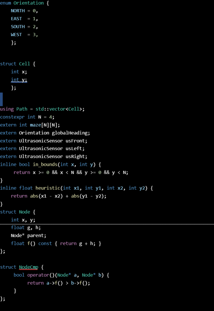
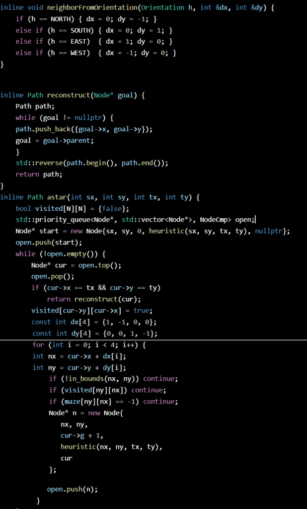
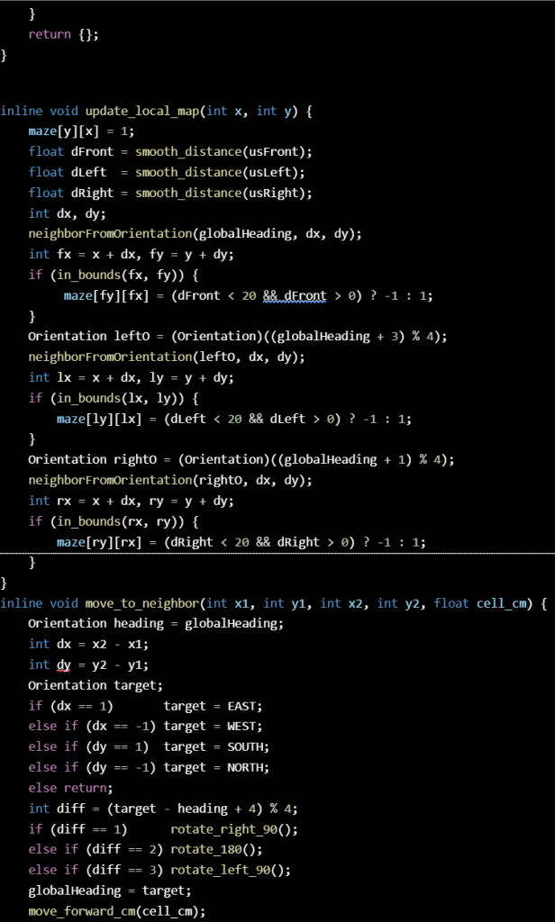
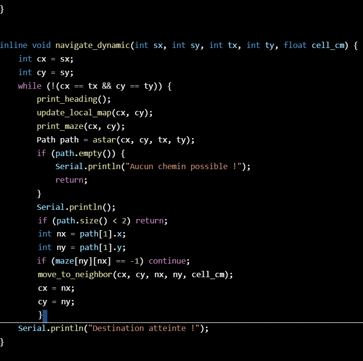
This week, I succeeded in upgrading the algorithm. It can now recalculate its path when there is something in its way. After each move, I check which neighbouring cells are available so I can update the matrix accordingly. Then, I update the car’s position and recalculate the path to the destination.
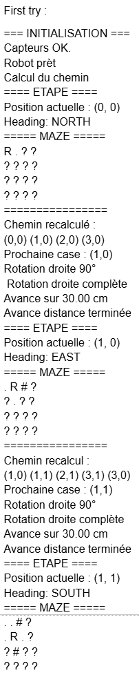
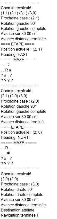
While testing, I discovered that the front sensor wasn’t working, but at the same time it proved that my code was working. At first, I wanted to test a basic path where the car only had to go straight forward with no obstacles, but since the front sensor detected an imaginary obstacle, it recalculated the path and that part was working correctly.
Here is my updated code and what it print while moving :
Anette:
This week I am still working on the PCB. It has been going a bit slow due to an upcoming exam and some major issues with orcad that lead to me switching to kicad. I have since been redoing the schematic in kicad and made a list over what i need to add to the board. I have also been working on how the layout should end up. Hopefully I will have time to finish early enough to order and test before the exam date.
Matias:
This week I didn’t make a lot of progress on the build itself because I was mainly focused on studying for the Electronic Design exam. Still, I managed to keep the project moving a bit. I met with Steven to make sure we have all the components we’ll need for the upcoming protoboard setup, so we’re ready to continue as soon as possible.
I also learned how to use the Analog Discovery, a portable oscilloscope. This will be really helpful, because now I can work with Sondre to check the PWM signals with the active filtering and see which filtering setup gives us the best results. Being able to visualize the waveforms directly will make it much easier to choose the right configuration.
Even though it was a lighter week due to the exam, I still picked up useful tools and prepared the next steps for the project.