Meron :
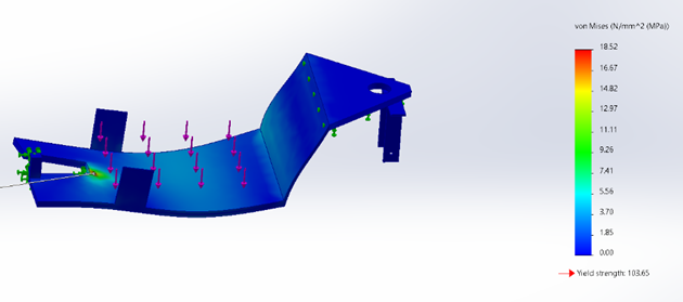
This week I worked on simulation testing in SolidWorks to find out how much weight our motorcycle frame can handle during balancing. Since our prototype includes several components such as the balancing motor, electronic systems and the spinning wheel, it was important to understand how the structure behaves under load. I have run several simulation tets with different loads, but I found the 10 kg test to be the most relevant for our design. This test shows the realistic limit for our prototype and gives us confidence that the structure is strong enough. I used plastic as material choice in simulation since our motorcycle parts are printed in 3 D which makes it important to understand how the material reacts under stress.
The first image shows the von mises stress, where the maximum stress is 18.52 MPA far below the materials yield strength of 103.65 meaning the part is safe.
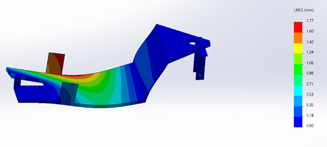
The second image shows displacement with a maximum deformation of only 1.77mm which is acceptable.
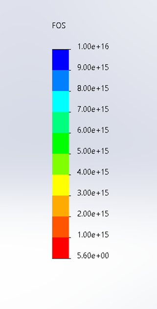
The third image shows the factor of safety (FOS) which is above 5 confirming that the frame is stable and secure.
Simulation is a very important part of our project . it helps us predict mechanical performance before building saving both material and time . for me as a mechanical engineering student this is valuable because it connects theory and practice allowing me to understand how design decisions affect the real performance of the motorcycle.
Salim & Muhammed Ø: This week we met and combined our code from last week. We set everything up, but we realized we had the wrong sensor. We were using the ADXL345, which only provides accelerometer data. In addition we tried to get readings from the sensor without soldering it, not knowing it won’t work, therefore we decided to wait for the MPU6050, which we will receive next week. We need the gyroscope as well, which we had discussed in the previous weeks.
We charged the new battery we received and discussed how we will test all the components on a bicycle now that we have all the parts we need. We also agreed on which balancing wheel we will use for testing. From there, we can observe how much the system changes.
In addition we have determined how to mount the sensor on the motorcycle, since doing this, we will be needed to change the code because the imu sensors axes. In the previous week we used the X axis, but now we will be using the Y axis, since it will be responsible for left and right.
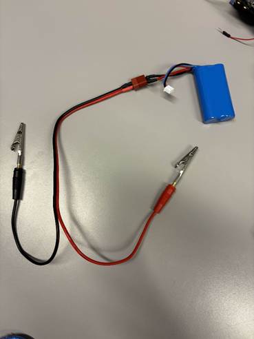
Furthermore we tested the system with the received battery and can confirm that it performs optimally for our purpose. The battery did not come with any cabels to connect to the system therefore we needed to find a way to connect it to our system. Our approach was by connecting alligator clips to the cables used to charge the battery, and then connecting it to our system with dupont cables. The batteries weight is enough to counter measure the weight of the motor, so it can be placed to achieve a balanced motorcycle.
we also changed minor things in our code amoung other things the complementary filter since it was wrong.
Our updated code:
#include <Wire.h>
#include <MPU6050.h>

MPU6050 imu;

// Filter og kontrollvariabler
float angle = 0;
float angleNOW = 0;
float gyroChange = 0;
float offset = 0;    // offset for gyroX
float a = 0.98;      // komplementærfilter vekting (kan justeres)
unsigned long timeLast;

// PID-lignende parametre
float X1 = 25.0;
float X2 = 0.9;

// Motorpinner (PWM-PIN for ENA)
int MotorENA = 5;     // PWM pin (må være PWM!)
int MotorIN1 = A0;
int MotorIN2 = A1;

void setup() {

  Serial.begin(9600);
  Wire.begin();
  imu.initialize();

  Serial.println("Hold motorsykkelen rolig for kalibrering...");
  delay(2000);

  long sum = 0;
  int samples = 200;
  for (int i = 0; i < samples; i++) {
    int16_t accX, accY, accZ, gyroX, gyroY, gyroZ;
    imu.getMotion6(&accX, &accY, &accZ, &gyroX, &gyroY, &gyroZ);
    sum += gyroX;
    delay(5);
  }
  offset = sum / (float)samples;

  Serial.print("GyroX offset = ");
  Serial.println(offset);

  pinMode(MotorENA, OUTPUT);
  pinMode(MotorIN1, OUTPUT);
  pinMode(MotorIN2, OUTPUT);

  timeLast = millis();
}


void setMotorSpeed(int speed) {

  // Begrens verdi
  speed = constrain(speed, -255, 255);

  if (speed >= 0) {
    // Motor fremover
    digitalWrite(MotorIN1, HIGH);
    digitalWrite(MotorIN2, LOW);
    analogWrite(MotorENA, speed);
  } else {
    // Motor bakover
    digitalWrite(MotorIN1, LOW);
    digitalWrite(MotorIN2, HIGH);
    analogWrite(MotorENA, -speed); // positiv PWM
  }
}


void loop() {

  int16_t accX, accY, accZ, gyroX, gyroY, gyroZ;
  imu.getMotion6(&accX, &accY, &accZ, &gyroX, &gyroY, &gyroZ);

  float dt = (millis() - timeLast) / 1000.0;
  timeLast = millis();

  angleNOW = atan2((float)accY, (float)accZ) * 180.0 / PI;

  gyroChange = ((float)gyroX - offset) / 131.0;   // deg/s

  angle = a * (angle + gyroChange * dt) + (1 - a) * angleNOW;

  int pwm = -constrain(X1 * angle + X2 * gyroChange, -255, 255);

  setMotorSpeed(pwm);

  // Debug
  Serial.print("Angle: ");
  Serial.print(angle);
  Serial.print(" | gyro: ");
  Serial.print(gyroChange);
  Serial.print(" | PWM: ");
  Serial.println(pwm);
}
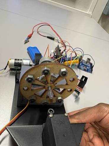
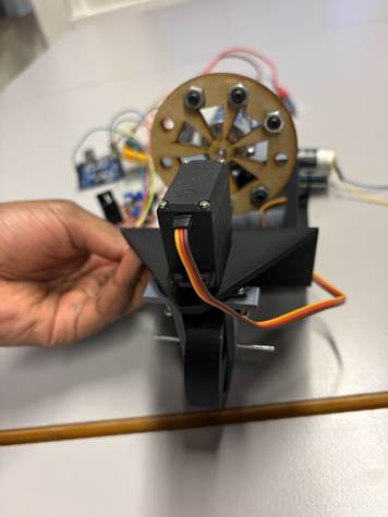
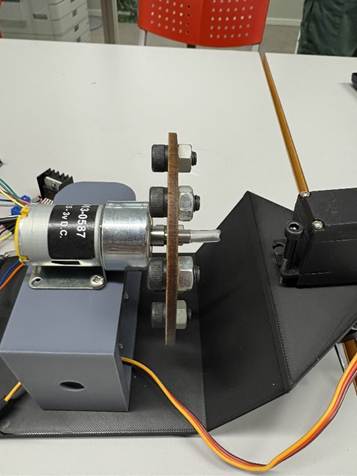
Picture of the connected components:
Muhammed Ø:
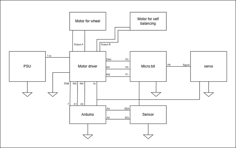
this week I worked on developing a wiring diagram for our system. The ground symbol indicates a common reference point. This ensures that all signals use the same reference voltages.
Mohammed A:
I worked in solidworks to build a front and back wheel with inmind to make everything look slimmer and better, and put as much weight in the senter as much as possible, front wheel rotat at 120 degres. I am in the making of suspentions at home and in the workshop. In addition I working on the back wheel to have Tron wheel look alike, It give a chalange to have the belt outside or connected throuth the insdie of the wheel. In the week I’ll work on FEM analysis to see accumulation of vibration, where most of the load and stress accumulates. While we are talking about FEM analysis, I looked into topoligy to build a much stronger bike that can withstand the stress and vibraton. Side note, I am trying to get in contact with the Kåre, if we have time to build a chastity of the bike using the labs materials.