Hello and welcome back!👋
Hydrawlics continues to take shape this week, with both the mechanical and software sides moving forward. The team has been focusing on various aspects of the system to bring everything closer to a full integration.
Here’s what everyone has been working on!👇
Fredrik:
As we move closer to the end of the project, my main focus is to get the hydraulic system fully working. With that, I started redesigning the cylinders in an attempt to reduce leakage. I think that the leakage of the cylinder in the last test was mainly due to missing o-rings. I have therefore bought a new set of o-rings so that we have enough to properly test according to the design, in addition to some more pvc pipe and epoxy glue. From the video it was obvious that the main point of leakage was the interface between the endcap and the piston. I have added another o-ring slot to the end cap to mitigate this.
After yet another round of printing, cutting and gluing the cylinders together, I managed to test the redesigned cylinders. With this test came both good and bad news. The positive part is that the interfaces that were leaking previously seem to be sealed. But of course when one gap is sealed, another one appears. It seems like the source of the leakage is now through the printed endcap. Luckily I think this might be an easy fix, by just increasing infill on the print and making the part a bit thicker. Fixing this will be my main focus in the days ahead.
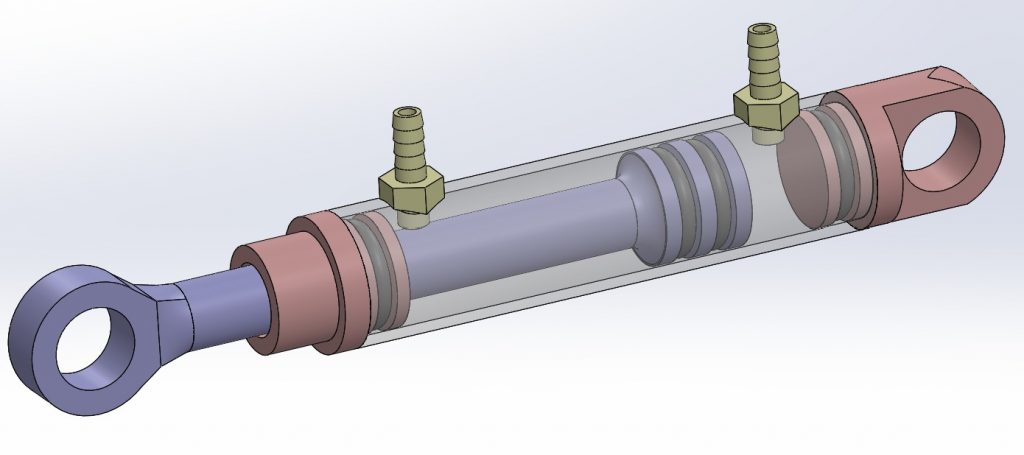
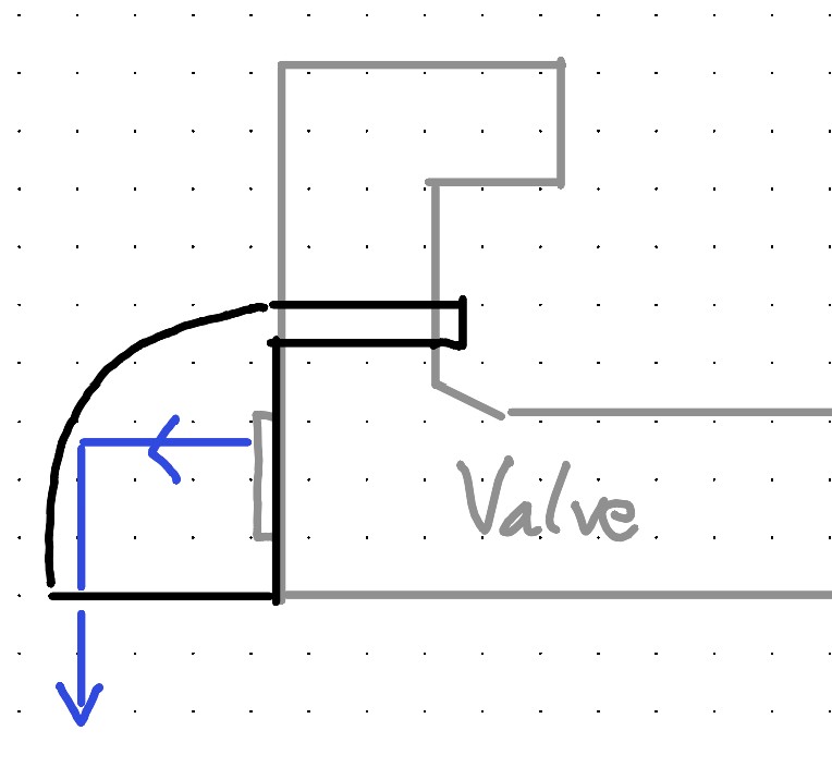
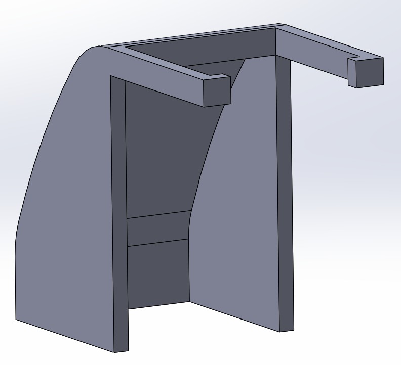
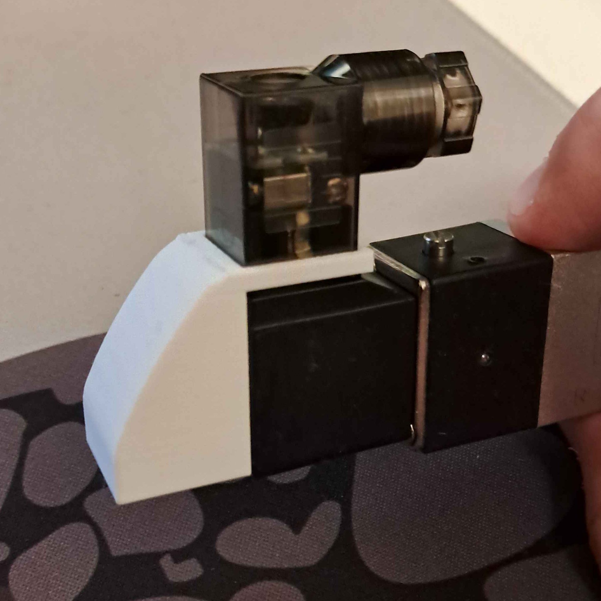
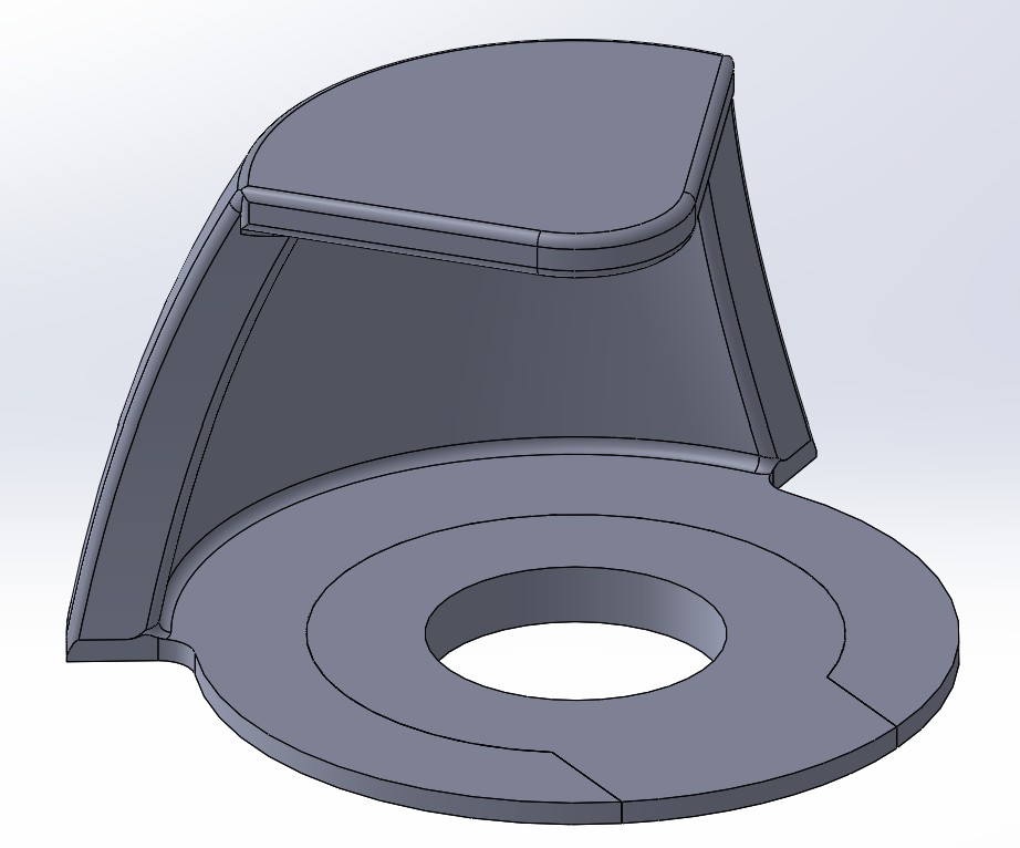
In the previous post I also talked about the chutes as a mitigation strategy for the water shooting out of the valve. I think this is because of the valves being pneumatic, not hydraulic. Because of this, hindering the water from shooting out might be risky. I have therefore designed some chutes to be attached at each end of each valve, to direct the water downwards, instead of shooting to the side. For simplicity’s sake, the chutes are designed to be printed and snap onto the valve. This week I have updated the design to the accurate dimensions, and printed the part. The snapfit attachment to the valve worked perfectly first try, which is rare. Without having tested the part, it at least looks like it will do the job well.
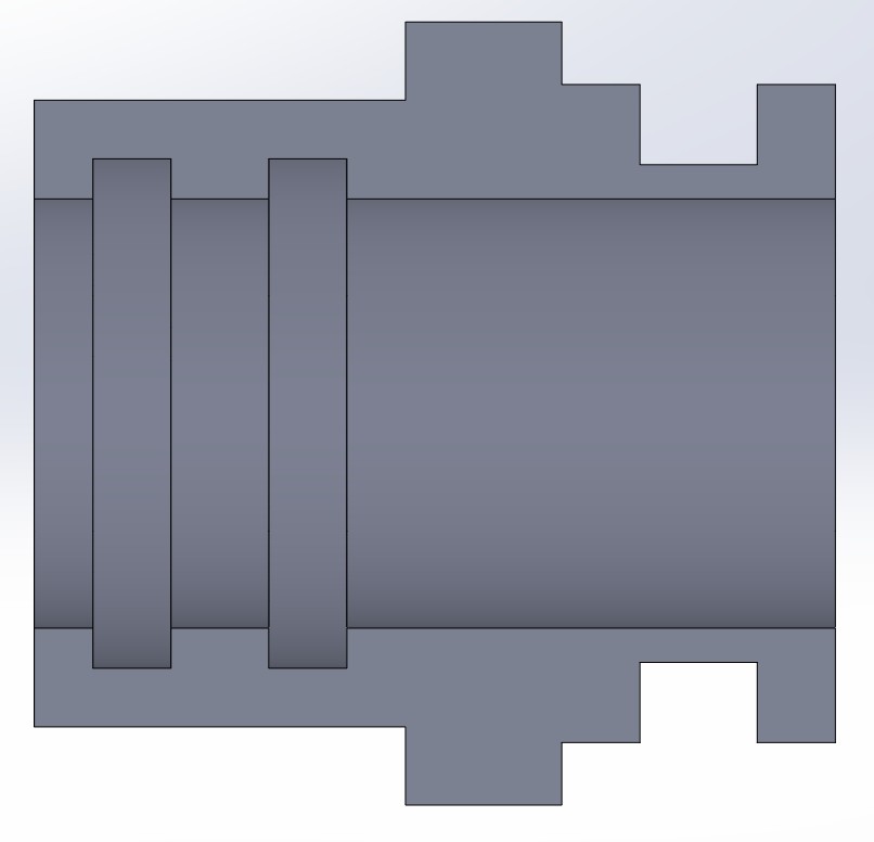
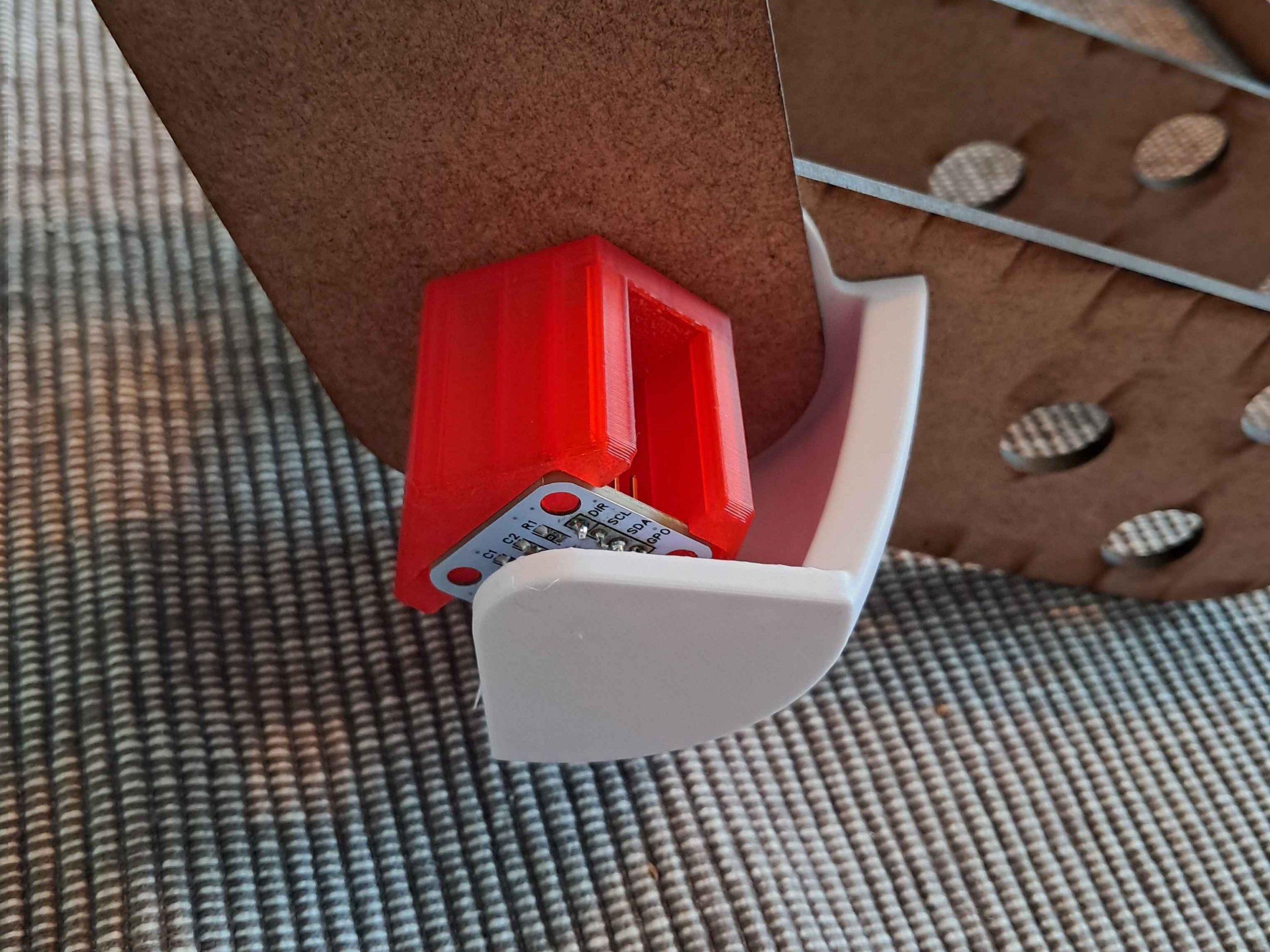
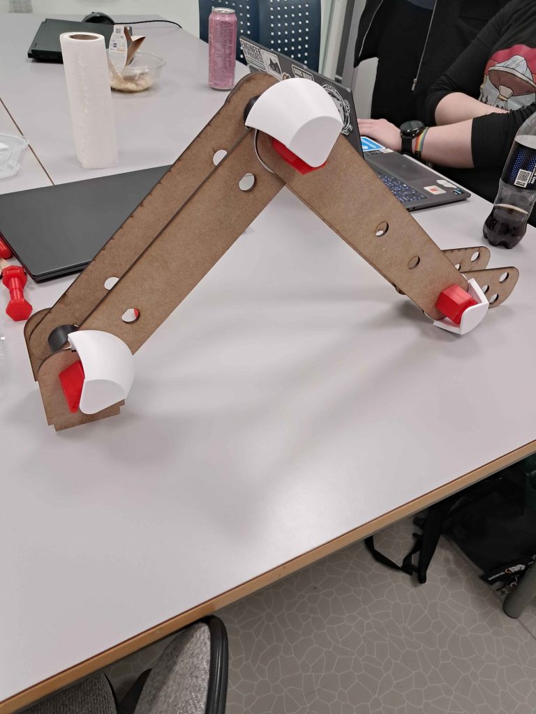
Last week I started on integrating the angle sensing system into the joint design. I redesigned the bolt to facilitate attachment of the sensor with the cabling underneath. This week I focused on positioning the magnet in the right place. It needs to be around 2mm from the sensor, and rotate around the same axis as the sensor and joint. I fixed the magnet attachment part to the bushing between the two arm segments, as I knew that would follow the rotation of the arm segment that was not attached to the bolt, meaning that the bolt and bushing follows different arm segments.
In order for the magnet attachment to go over the bolt, I needed to figure out some way to attach the bolt first, and then have the bushing with the magnet attachment. I was focused on having the magnet structure as stable, to not mess with the sensor data, so building the magnet attachment up with pressfit parts was unideal. Instead, I split the bushing into two parts, one that was attached to the joint before the bolt, and one that could slide in after the bolt. I designed them to lock into each other like puzzle pieces, to ensure that they moved as one part. (It is difficult to explain the part, so it might be best to take a look at the pictures below)
The magnet is going to be glued at the top of the overhang, and the part is designed with a small hole at the top to be able to poke the magnet out if we need it. Each magnet attachment part needed to be designed individually to accommodate for the available rotational area between each arm section. In the interest of designing the part to be stable, I wanted the wall to take up as much of this space as possible. After printing the part, it seemed like everything fit together nicely. It was a bit of a task to get all the magnet attachment parts in place, but after a while I got the hang of it. Check out Lisa and Syver’s post to see how the angle sensing system implementation went on their side.
From the mechanical side, it is critical that we get the hydraulic system up and running in the coming weeks. We are very close to a working system, and it will be really cool to integrate it with the arm structure.
Lisa:
This week, the focus has been on building the software foundation for our new rotary-encoder system. With the AS5600 magnetic sensors and the TCA9548A I²C multiplexer prepared from last week, I moved on to implementing the software logic that will replace our old potentiometer setup.
I’ve been developing a dedicated RotaryEncoder class, which is responsible for handling all communication with the encoder hardware. The goal was to create a clean, modular, and maintainable structure that can easily be reused for all joints later on. The class now takes care of selecting the correct multiplexer channel, reading the AS5600’s 12-bit angle value, converting that raw value into degrees, and applying an adjustable offset for calibration. I also added support for saving and loading this offset using EEPROM, so the system can remember its zero-position between restarts.
Even though the software side is implemented, the actual testing has only just begun. The encoder is responding through the multiplexer, but the readings are still a bit off. Syver had the main responsibility for the calibration work, especially when it comes to handling offsets and aligning the zero-position, which will be crucial once we start refining the behaviour further. Overall, this has been a productive week of laying down the groundwork. The next step will be hooking the module up to the physical setup and making sure our angle-reading pipeline works from end to end.
Syver:
Hello again! Last week saw some work around the Arduino-RPI protocols and some wiring. This week was mostly the same, soldering up some wires and working on components needed for integration between systems.
I started the week by wiring up the cables needed for the valves. This wasn’t complicated, but it was tedious. Each solenoid valve consists of two coils, one for each output flow. Both coils need both ground and voltage. To reduce clutter, I soldered a jumper wire to bridge the ground connections of the two coils. This reduced the amount of wires per valve from 4 to 3, but we still needed 12 cables in total.
We also needed a way to easily wire them all together. After testing the integration in week 11, we realized how hard it was connecting 6 cables to the same Wago or terminal block. During the same test, we measured the solenoid coil current load to be 0.25A. Through some research I found that breadboards could handle up to about 1A of current, preferably with under 5W of wattage. We will run at most four coils for a very short time, maxing out at 1A. So I soldered breadboard pins to the other side, giving us the flexibility to use breadboards for easy testing and debugging. For continuous operation, we will switch over to hardwired terminals. After spending a full day assembling, I tested them. They all worked!
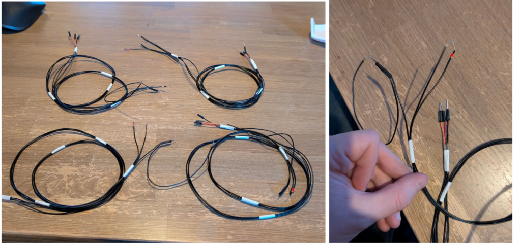
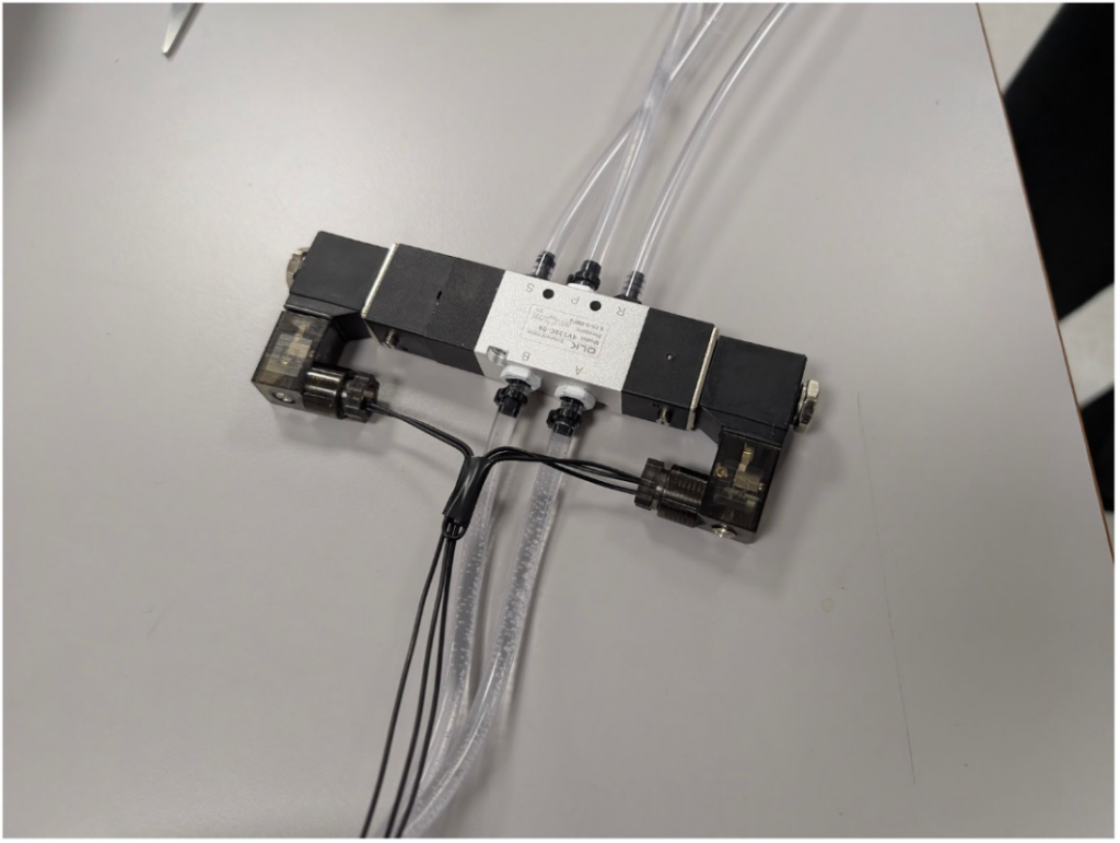
This is how they’ll look connected.
The latter part of the week, I cooperated with the others in integrating our system together, specifically the rotary encoders in the arm joints. Me and Lisa started coding the adaptations needed to switch from potentiometers to the AS5600 rotary encoders. It went smoothly for the most part, much due to the modularity of our kinematics codebase. I mainly worked on integrating RotaryEncoder into the Joint class, while Lisa worked on the internal RotaryEncoder functionality.
After this, I worked on integrating a calibration system for the arm. Hall effect rotary encoders like these use edgeless magnets, making it hard to mount them at a set absolute angle. We therefore needed a calibration system where we could push a button to set the offsets in the RotaryEncoder class. This worked out well, but needed some attention to detail when implementing the maths. By the end of the week, the calibration functionality operated successfully.
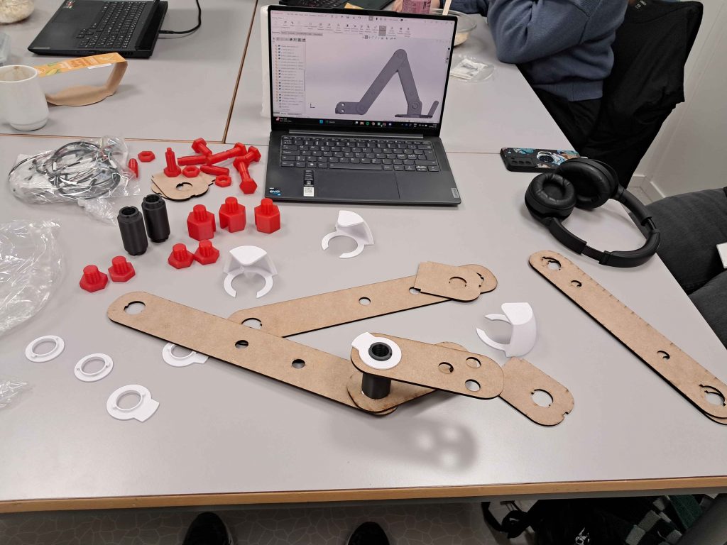
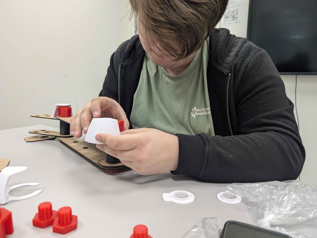
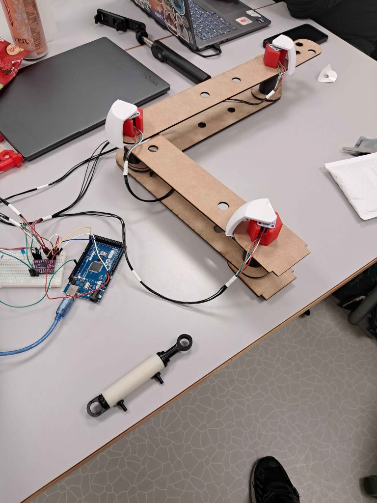
This gave us everything we needed to test the arm angle readings while articulating it. See pictures in Fredrik’s section for the assembly. Much of the testing went smoothly, with each joint working as expected. However, two of the sensors showed jumpy readings periodically. Worried they were broken, I ordered some more in reserve. Hopefully resoldering the header pins will fix them.
During testing, we could also see the calculation of the piston lengths live. Most of the joints showed correct calculations, except the bottommost joint at the base. The last few hours of work this week therefore went into debugging this.
This brings us to me writing this, right now. Hello!👋 I realize I probably need to pick up the maths I did a couple of months ago to visualize and debug the problem. It will definitely be a couple of tedious hours of troubleshooting. We are, however, really close to having a fully functioning control system, serving as more than enough motivation. I think we’re on track!
Emory:
This week, I focused on fixing so that you get the G-code from the image that is loaded up to the website, so that it can be sent from the Raspberry Pi to the Arduino to give the arm movement. I did this by adding to main to extract the coordinates from the image sent, so that it can be converted into G-code.
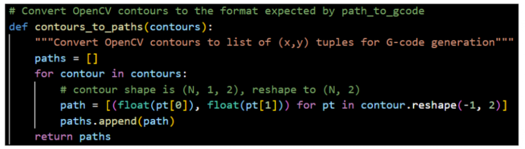
So for this, I needed to make sure the polygon numbers and their corresponding coordinates get reshaped into (N, 2) a list of (x, y) from (N, 1, 2), so that’s it in the expected format for G-code.
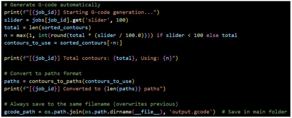
The second part is auto-generating the G-code from the finished generated image based on the amount the slider is on to get the correct number of coordinates based on the contours someone wants. It takes the largest N contours and converts them into a path format. This then generates the output.gcode file inside the main folder, so it can be found and used later when sending it to the Arduino. The path then gets stored inside the job data.
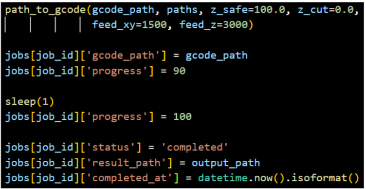
The path_to_gcode converts polygon coordinate paths into G-code commands for the arm movement.
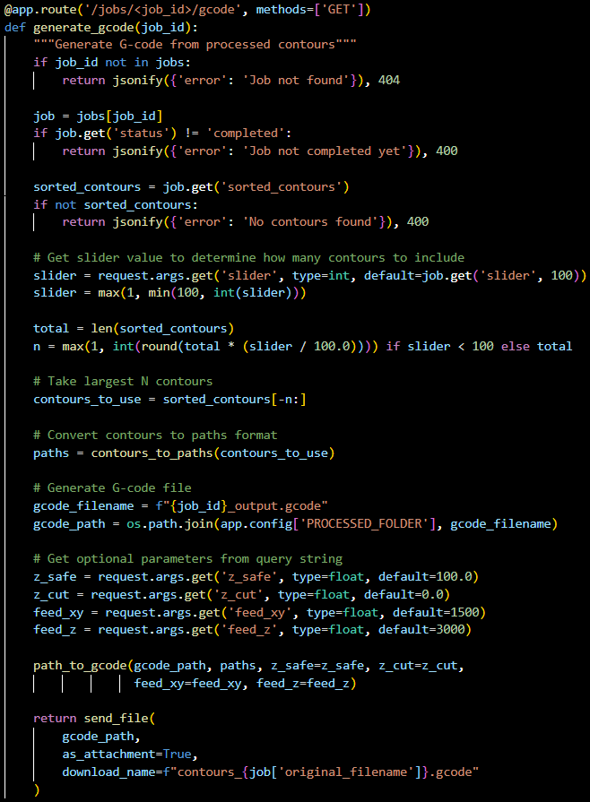
The last part allows for downloading the G-code with the specific parameters that are selected using the slider for each generated image. It creates a path based on the sorted contours so they can be sent.
Erling:
This week I have been focused on the supporting pieces for the system. Namely a box to house the valves while the system is in operation. as there will some leakage due to the fact that the valves are meant for use with air, and not water. This water leakage is unavoidable in our current system, and so we must account for it in building the demonstration system.
I have also worked on a setup to allow the arms base to pivot, so that we can unlock the last degree of freedom for our system. I will be talking more about both these parts during the blogpost.
New manifolds.
As the small printed hose clamps failed last week, i decided to remodel the manifolds so that they are one singular piece. This removes the need for assembly of this part, but means that the whole manifold is unusable if one hose barb breaks. (This was also true of the last design.)
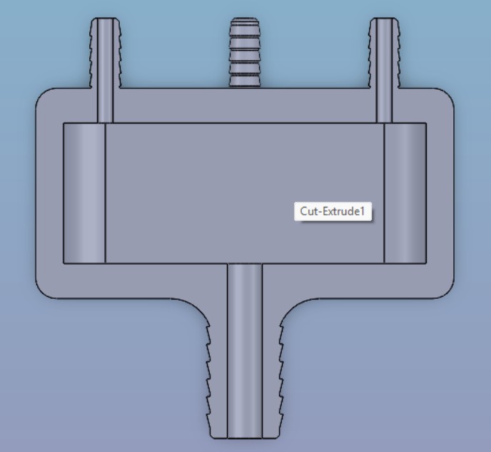
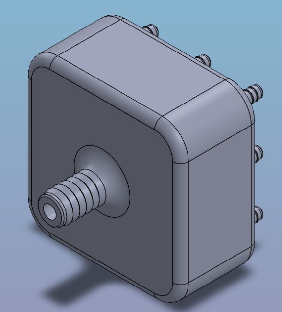
I tried a few times to print these in ASA, but had horrendous results with the parts adhering too well on the build plate and having to break them to remove from the printbed. So i have Printed a few Specimens in PLA and expect some to break. i plan on printing them again when i can get a hold of some PEGT, as Fredrik has shown that PETG has a much better layer adhesion than PLA and is less prone to water absorption leading to embrittlement of the material.
Azimuth axis cylinder placement.
In previous blogposts i have talked about how we have made the arms base be able to rotate, and how our radaxial bearing design works. But until now we have not had a way to reliably control the polar position of the base using the piston cylinders that Fredrik have made. This week i have made progress toward this goal.
It started relatively simply with determining the stroke length of the piston. and see what polar movement we can get when placing the pin on the base a certain distance from the center of rotation. Then i moved the “anchor tower” around a bit in order to determine where it should be located relative to the base. The result of this experimentation looks like this, very rough, but enough to inform a new iteration.
After changing the positions some more, i landed on new positions and decided to extract the necessary dimensions in order to do detail design on these parts, and get them printing. The parts ended up being simple, and i think that is a good thing, as they were easy to print and have ready for testing in the near future.
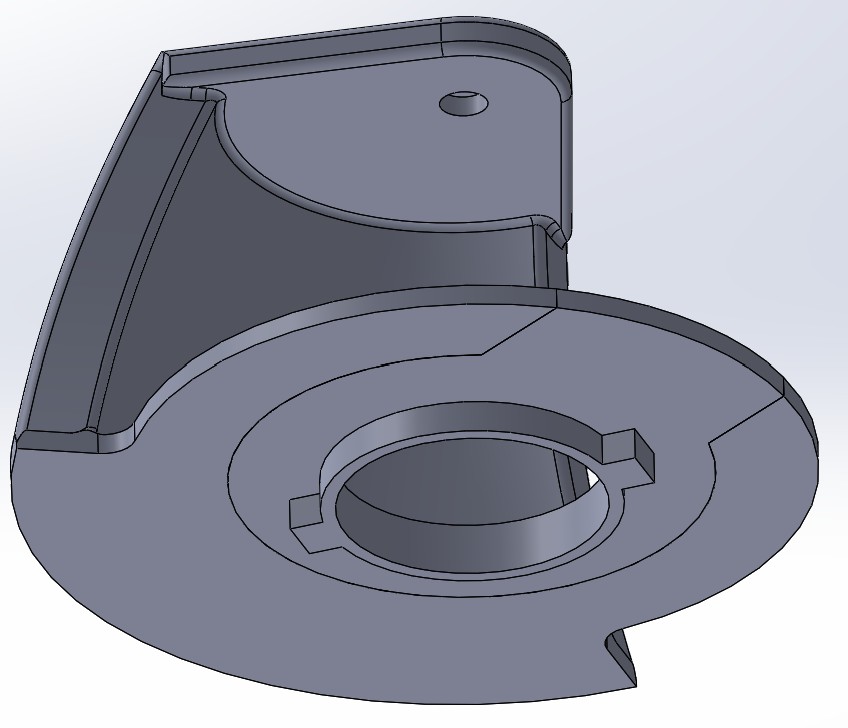
Valvebox assembly.
Because the valves we are using for the project are really air valves, they are not really water tight, and as such will leak no matter what we try to do about it. This is the same reason why Fredrik has made the spray deflectors. We want to be able to put all the valves into a single box and contain the spray while keeping the electronics up and out of the way. This tast fell to me, and i answered it with this box.
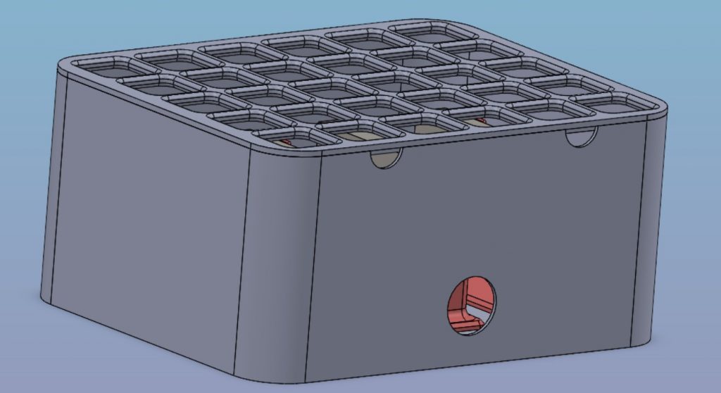
As we can see, it has a lid that has a grid in it, this is so that we can run all the electronic power and control wiring up and away from the water. There are two semicircular cutouts along the top in order to allow us to run the A and B lines from each valve to their respective piston on the arm. The cutouts are sized to pass through 4 lines each, and 8 in total. as there are 2 active hydraulic lines for every piston cylinder.
Lower there are holes in the wall in order to pass through the input lines from the distribution manifold and the output lines to the collector manifold. These along with the pump itself will be placed outside this box.
Here is a top view of the same box, to show that i have implemented a drainage hole in the bottom of the box. We do not expect a large amount of water to gather in the box, but it is better to have the option for drainage than need it retroactively (though that would be easily fixable with a drill.)
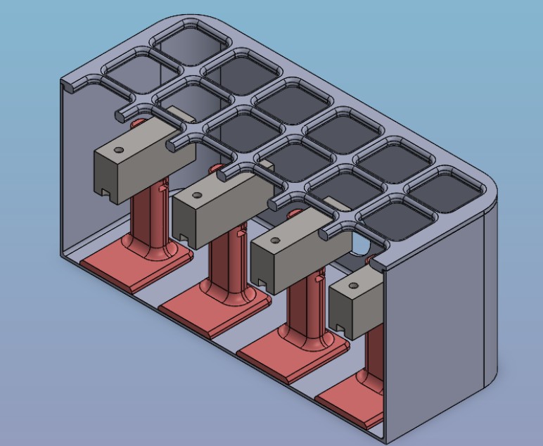
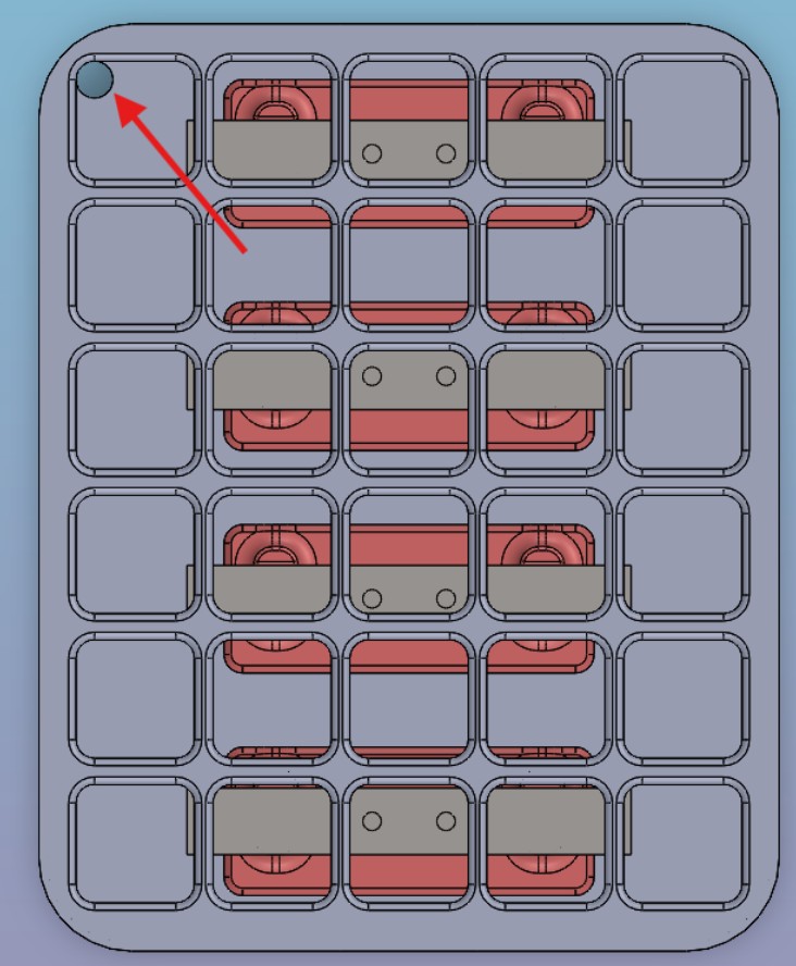
I will also include a Section view of the assembly, in order for the reader to get an idea of how the valves will be situated in the box, and the amount of free space we have. This is the largest size box i can print by myself without breaking it into pieces.
That’s all for now, see you nest week!