Wang
This week I’ve continued working on the BitPayer joystick. I have now managed to get contact with and readout to the serial monitor this week.
Now the next step is to set up Bluetooth again and then send the data over so that I can control the other micro:bit with the controller. I might be able to use the same settings as the Pong game on SDK v3.1.1 but adapt them to SDK v2.5.1.
Henning
So as my status for last week. I ran away from the whole idea of implementing the “QtMqtt” library. The whole thing became a bigger obstacle and only consumed a lot of time with no result. I was simply not able to download it into QT. So, i did some more research and read up that i can simply set up the AI to the Rasp Pi with just some simple code. Depending on how i do it, i can either make the AI operate through the Rasp pi or through my GUI. So coming week, i will try and work closer with Zardasht to see if this is something we can simply put together.
So i am left with a lot of option coming this week and can then hopefully show you some progress through pictures or videos soon enough again.
Oskaras
At the start of the week when i plugged in my car to just see it spin it didn’t work as intended. Most wheels were spinning while some were not. After some testing with different iterations of the code i accidently touched one of the black parts on the driver.
It was very hot. The power supply was also struggling since it started to send like 2,7 amps just to stabilize the voltage. i turned the power of and disconnected while waiting for the driver to cool down. After checking every spot that was supposed to give electricity from the micro-bit to the driver i concluded that the issue was not properly secured wires. After wards the supply got back to normal sending only about 0,5 A to power the whole car and all the wheels were spinning. I also looked into the driver some more and found out some more thing about it:
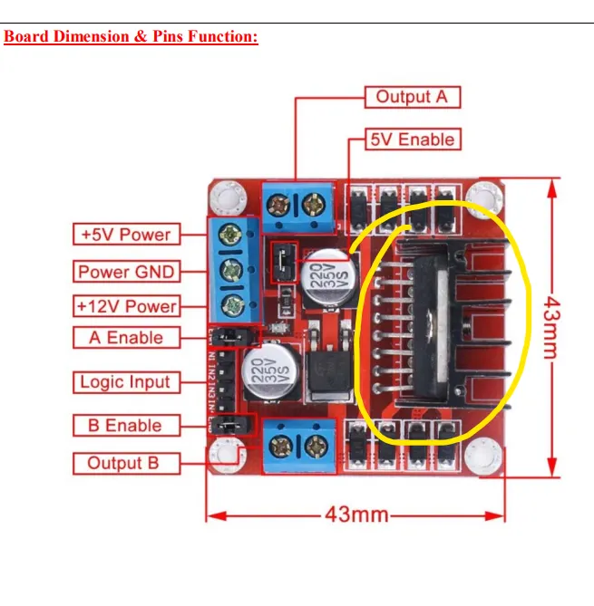
- The 5V was an output from the driver not an input and that you needed to use the jumper to activate it
- Also the other power source was the input and that the driver can take anywhere from 5 to 35 V in there.
- a singular driver has an internal resistance that causes a 0,7 V drop. hence why i now supply it with 7,4V since: 7,4 – 0,7 – 0,7 = 6V
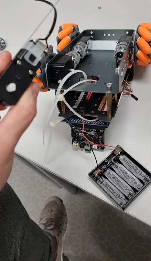
Here is a showcase of me using the library i created.
The forward was working perfectly even with the optional singular motor control as well.
The issue began when i tired to reverse it. Of course one of the wheels didn’t spin. That is when i found out that pin 8 on the edge connecter didn’t work. i swapped it for another pin and everything worked perfectly. i Also tightened absolutely everything to get rid of any inconstancies there.
https://youtube.com/shorts/9tj-1Yepcgk?si=fjDb3pTthQzDAyq8
The second problem was when doing the singular wheel function on all wheels and using an alternating period rather than full power on the pwm sometimes the back wheel wouldn’t spin. But it was inconsistent and would alternate between spinning and not. So I went ahead and uninstalled the motor, tired another one.
After letting it run for 20 iterations i concluded that it was something wrong with the motor
Also this is the commit for the motor controls implementation into the main
https://github.com/OskeLTU/Zephyr_code/commit/5097d7aa4ccdf31b04bda183909de86f7bd97ada
The way i work on GitHub is that i have the safest working version on the main branch this is the most stable and bug free. and i have another branch where i implement new things. i only merge and update the main when the alternate branch is working close to 100% as intended, or without any visible bugs.
Zardasht
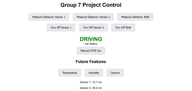
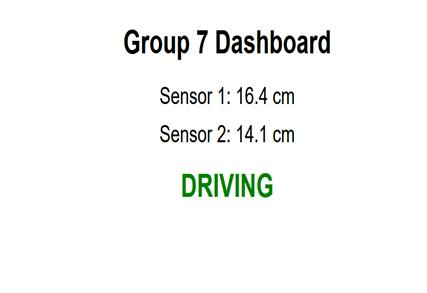
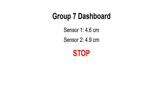
In our Group 7 project, I installed and configured a second ultrasonic sensor on the Raspberry Pi. Both sensors now read continuously and display their data together on a web dashboard. Using Flask, I built a simple interface that updates in real time, showing distances and a clear status: STOP when an object is closer than 5 cm, and DRIVING when it is safe.
The dashboard has a clean grey background and includes extra buttons for future features like temperature, humidity, and camera. These are not yet active, as we await the final group decision on what components will be mounted on the car.
The photo below shows the dashboard in action, with both sensors actively measuring and displaying live distances. The interface also includes future feature buttons and a clear status indicator showing the car is currently DRIVING.
Øivind
Follow up on my disclaimer last week: Something went wrong last time because of the format I sent our Blogmaster. But today he fixed it by adding links to vids instead of embedded vids.
We start off the week like this:

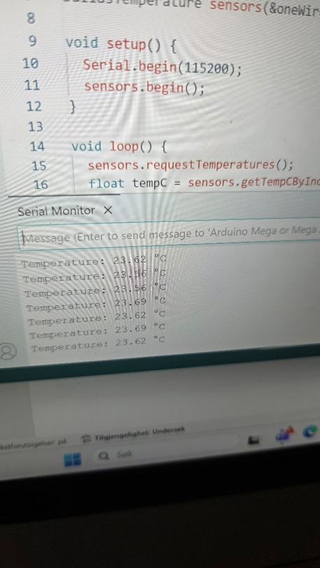
The temperature sensor was working. I have been violent when assembling the battery-pack and have pulled a pin off. Tried different temp. sensors, but the first one was easiest to get good readings from.
Richard came to me in Dronesonen, and now I know what he needs to help me. I will start drawing by hand some sketches he can use.
I will postpone the logic for the charger and get back to it if I get time later. I will try to get the power output to the Micro:Bit today, I see the guys struggle with their power-supply and hope they can start trying out the stand-alone battery-pack this week. Delivery of small parts takes more time than expected, so I will, with what I have now to start the different modules of boards. Power-board, Logicboard and some boards for the sensors.
Under I test the microphone. I struggle to make it read the signals from the beeper, but from my voice and whistle it works. I guess it needs more calibrating or maybe some amplifying, I need to check how the microphone works, because it might handle lower frequencies better by the way that it is made, or some fault in the diaphragm (If that is the tech it uses). After I checked it further, I got good signals, lighting up LED on both sensor-board and on the Arduino Mega. But if this will be enough and applicable to use the solution, I still do not know.
https://vimeo.com/1135386443?share=copy&fl=sv&fe=ci
An app I have used for a while shows the frequency of the sound. This was measured using von Hann window in Spectroid There are different window options I can use and cannot show everyone. But a rectangular window gave good measures.
Tried Arduino
https://vimeo.com/1135399528?share=copy&fl=sv&fe=ci
The plan is to filter out the signal with a bandpass filter, so I can suppress the unwanted noise.
Angel Hair Wires
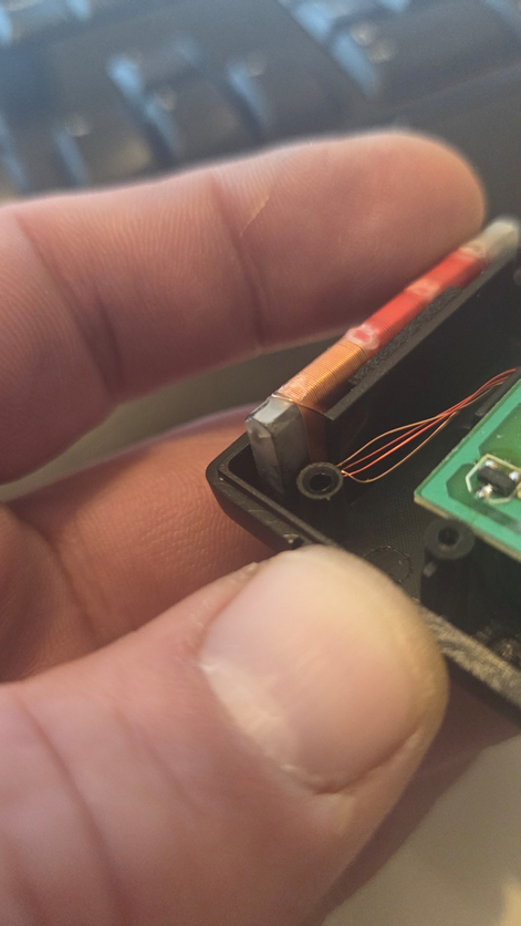
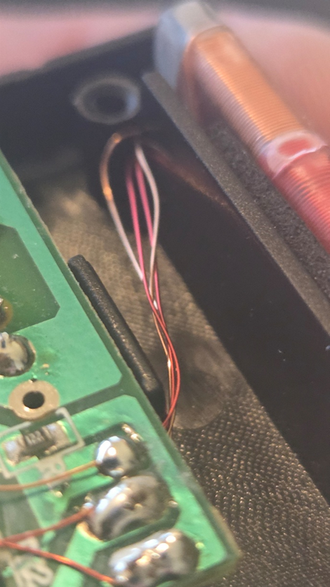
Pictures above barely visualize how extremely thin those leads are. I need to work up some courage to disassemble that board from the chassis.
WELL, THEN! FML!!!
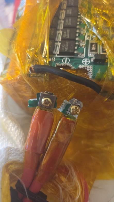
I have another BMS, but I’m afraid it got damaged when I tried solder it for the first time. That’s why I terminated this BMS with screws to the 12AWG cables this time, the thick wires stole so much heat that I did not manage to melt the solder without external pre-heating. I will desolder this BMS but test the other first. I get readings of correct voltage through this, but I cannot trust that I will get this board to work properly regarding robustness.
Drawings to Rickard is finished and I in addition will ask for other add-ons I have most other parts ready for. My mind contains a castle I only started finding the property for. Yet contrary to Kan-Ban method I like to keep options open on a project like this, since I can always scrap what we do not have time for or do not get to work properly.
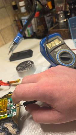
Checking the power-supply/charger, and untouched the step-down converter has dropped from 12.7V to 12.5 V.
https://vimeo.com/1136030052?share=copy&fl=sv&fe=ci
It’s ALIVE!
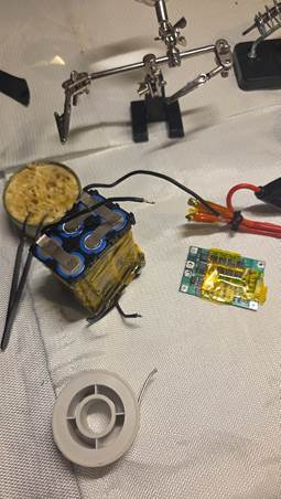
I read correct values from the other BMS, so it works. I desoldered the broken one, and this time I will mount the BMS in a way that it’s less strain on the connectors. I will wait for recommended soft tape before I assemble the pack again.
Wow! Feeling quite proud of myself. It’s not much, but it is the first digital signal-processing I have done outside of a classroom. The code uses the FFT to capture the frequency from the beeps. Because of the 500ms on/off beeping signal I had to work around that by having the Arduino wait for consecutive beeps before alerting. This took a while to finish, because I used an alias of my desired signal for too long. I switched from rectangular and von Hann window (tried before, but meek results) to Hamming window both in my Spectroid app and in the code. That worked. Black magic I see there is potential for the code to perform even better. But for my purpose, on this exact function I think it is good enough. Video under. Turn sound on.
https://vimeo.com/1136140707?share=copy&fl=sv&fe=ci
After this video I tweaked the code a bit. I used a sample frequency at right over 5kHz. Showing signal frequency at around 1900Hz.
https://vimeo.com/1136856549?share=copy&fl=sv&fe=ci
Right when I got proper results, my Arduino Mega died on me. Maybe I should use the Micro:Bit since the software guys use that. But I do not have all necessary parts right now. Also, Micro Python have no good library for the FFT and the Arduino Library in C++ will not work directly with the Micro:Bit. I will seek advice with Steven this coming week.
I will start on the power-board once I find the most suitable voltage for the motors, thinking 6-12V. The board will supply 5V to RPI and Micro:Bit through a buck-down/step-down converter and through an LDO 3.3V because some sensors behave best with 3.3V (at least from the Arduino Mega) even when rated supply is between 3-5.5V. About the main switch for the power, I have a problem with how I will properly fasten and isolate it. Now my imagination shows it will look messy, but I will find a good solution soon.
A small number of analog filters will be implemented if the capacitors arrive in time. ATM I only got one earmarked for the power-buses.
I will create a board with shift-registers in case we need them. The same board will carry two or three ADCs for analog sensors, because we are running out of analog pins on the break-out boards.
I think I will swap the L298N drivers in favor for BTS7960 if I find the space, which I might since I will get more space to use underneath the top of the chassis.
| Column1 | Column2 | Column3 | Column4 |
| Header Pin | Signal | Connector Type | Description |
| PWR1-1 | VBAT+ | XT60 | Battery positive input |
| PWR1-2 | VBAT- | XT60 | Battery negative (return path) |
| PWR1-3 | 5V OUT | JST-XH 2-pin | 5V regulated output |
| PWR1-4 | 3.3V OUT | JST-XH 2-pin | 3.3V regulated output |
| MOT1-1 | MOTOR1+ | Screw terminal | Motor driver output A+ |
| MOT1-2 | MOTOR1- | Screw terminal | Motor driver output A- |
| MOT2-1 | MOTOR2+ | Screw terminal | Motor driver output B+ |
| MOT2-2 | MOTOR2- | Screw terminal | Motor driver output B- |
| SENS1-1 | IR_SENSOR_VCC | JST-XH 3-pin | Power for IR sensor |
| SENS1-2 | IR_SENSOR_OUT | JST-XH 3-pin | IR sensor signal output |
| SENS2-1 | DIST_SENSOR_VCC | JST-XH 3-pin | Power for distance sensor |
| SENS2-2 | DIST_SENSOR_OUT | JST-XH 3-pin | Distance sensor analog output |
| I2C1-SDA | SDA | 2.54mm header | I2C data line |
| I2C1-SCL | SCL | 2.54mm header | I2C clock line |
| ADC1 | ANALOG_SENSOR1 | 2.54mm header | Analog input channel 1 |
| ADC2 | ANALOG_SENSOR2 | 2.54mm header | Analog input channel 2 |
| GND1 | GROUND | Through-hole pad | Ground reference |
| GND2 | GROUND | Through-hole pad | Additional ground |
| TP1 | TEST PAD 1 | Test pad | Voltage test pad |
| TP2 | TEST PAD 2 | Test pad | Current test pad |
| TP3 | TEST PAD 3 | Test pad | Signal test pad |
| TP4 | TEST PAD 4 | Test pad | Control test pad |
In addition to this list there will be several capacitors, RC snubbers and some transient voltage suppressing diodes.
I’m struggling a bit with what I want to implement since the “software-guys” have their hands full. I still do not have motors with encoders. I hate to see that we end up with a “bare-metal” Moon-Rover without proper feedback systems. But me alone can only do “so much”. I will not be able to implement all feedback systems, since now I feel like that is giving the rest of the team a headache to implement. I read Zephyr is great at those things. But I’ve also been told, Zephyr is like a nasty version of your mother-in-law.
After hours of searching for errors and correct codes, I found out I need a voltage divider for the analog temperature sensor. This will affect the space I have at dispose. The digital sensor has a potentiometer that I’m afraid can break if I put it on the battery-pack- I will keep it as an option. The voltage divider circuit will not be any better.
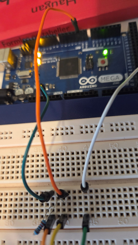
I got one more card up my sleeve. The DS18B20 one-wire digital temperature sensor. With this I can use only one data line and ground. It can derive power from the data line (called “parasite mode”), which eliminates the need for an external power supply. This is particularly good for this sensor as I do not need to wire back more than a data-line, I can connect ground at power-supply negative side, the same place I connect the ground-bus.
(Ended up with three wires and a pull-up resistor as this gave the result I want)
I went back and forth between the sensors. I settled on the smallest digital one, because after two/three more hours of testing, I got the correct readings from the DS18B20 temperature sensor.
All I needed was a voltage divider between 5V input and the data line. -YEP!! Just like the analog, yet I liked this one better because of size and performance-. In lack of other values, I used a 10Kohm, but my analysis shows a 4,7Kohm will be better suited.
Today was productive! Voltage Divider, Drawings to Richard, Charger calibration, Testing former BMS, Solder jobs and the thermometer!
I should have read about electromagnetism and about control systems today. But you know, when you have a lot of boring stuff to do, the dirty dishes are alluring.