Sondre:
I’ve been following a guy on YouTube called Stuff Made Here, and he creates some really impressive projects that combine a lot of programming with mechanical design. What I’ve learned from watching him is that things rarely work perfectly the first time, you often have to dig through every little part to figure out what’s wrong, also known as “integration hell.” That’s pretty much what my week has looked like. I’ve been working on integrating the encoders properly, but it’s still a work in progress.
Where I left off last week, I had managed to get the encoders to send signals to the Micro:bit and print the values in the terminal. However, the data coming through was completely incorrect, just random gibberish instead of meaningful numbers. So, I started focusing on getting sensible values from the encoders.
After some debugging, I discovered that the issue was caused by a mismatch in how data was being sent and read. The ESP32 was configured to send eight 4-byte numbers, while the Micro:bit was only set up to read 2-byte values. Because of that, the data was misaligned and unreadable. I had to adjust the data format and communication protocol so both devices used the same structure. Once that was fixed, I finally started getting stable and correct readings from the encoders, which felt like a big step forward.

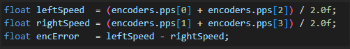
Here you can see that I’m successfully receiving pulses from the encoders, two positive and two negative. This happens because the motors on one side are rotating in the opposite direction to make the robot move forward. I also implemented a simple counter to keep track of the distance traveled.
I then decided to create a new PID controller in a separate library folder to avoid breaking the one I had already made. The new controller reused much of the logic from the previous version that handled the IMU and wall sensors, but this time I needed to include the encoder feedback. To keep things simple at first, instead of controlling each wheel individually, I implemented it so that each side of the robot would spin at roughly the same speed.
By constraining the PID output between -1 and 1 and applying the correction to each side, the robot should achieve a more accurate wheel speed balance. In theory, this means the car won’t have to rely as much on the IMU for correction, since the encoder feedback already helps keep it driving straight.
But, as people like to say, theory and practice aren’t always friends. After I added this part, the problems just started stacking up. The first issue was that the IMU suddenly stopped sending data. That told me there was a collision on the I²C bus. Since the expansion board only has one I²C bus, both the IMU and the ESP32 had to share it. When the Micro:bit tried to request data from the ESP32 and the IMU at the same time, the IMU stopped responding.
The workaround was to slow down the ESP32 updates — I changed it so the ESP32 only sends new data every 1000 ms. That makes the data refresh a bit slower, but it prevents the I²C collisions and keeps the IMU alive.
Next came another issue — only the front wheels were turning. Great, more trouble for me. This turned out to be the same problem I faced earlier when integrating the PID controller with the IMU. It showed that the rotation input was overpowering the forward motion input in the mecanum wheel calculation. To test this, I set the rotation value to 0 and voila, all the wheels started spinning in the same direction as they should.
Before I even got the chance to solve the rotation issue, I ran into a new or rather, old problem. All the sensor values, except for the encoders, started dropping out while the robot was driving.
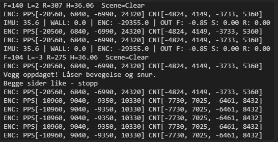
This often happened whenever the robot detected a wall, as shown above. No delay or other quick fixes seemed to solve the issue. So, I decided to unplug the servos from the expansion board to free up a few pins and try using a SoftWire IIC setup instead. After downloading the SoftWire library, I initialized pin 0 and pin 1 as the SDA and SCL lines and connected the ESP32 to them. But, as you might guess from the rest of this blog post a new problem appeared.
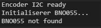
When I tried running a Software IIC connection on pins 0 and 1 of the Micro:bit expansion board with the ESP32, the IMU suddenly stopped responding. That was because pins 0 and 1 aren’t real IIC bus, they’re general-purpose pins, which turned out could not be used as Soft IIC bus, making communication unstable. The actual IIC pins are 19 and 20, so using 0 and 1 causes signal problems and conflicts with other devices.
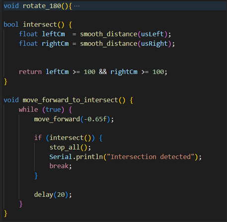
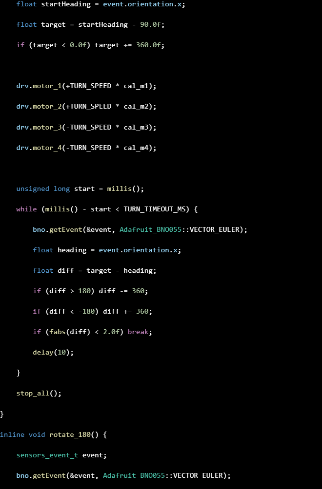
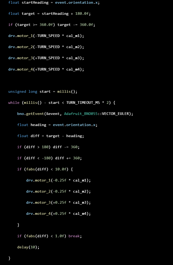
Since Theo is developing a maze-solving algorithm, he needs additional functions to handle the car’s movement. To contribute, I spent some time this week implementing a few extra movement features. I created a turn_180 function that rotates the car 180 degrees, as well as a function that detects intersections. This allows the car to drive forward until it reaches an intersection and then make decisions based on the available paths.
After spending all of Monday and a lot of Tuesday testing different solutions and troubleshooting, I decided to take a break and return with a fresh mindset. I also need to focus a bit on my other subjects since exams are coming up soon. Hopefully, all these problems are solvable and not a sign that the Micro:bit simply isn’t powerful enough to handle everything. If that turns out to be the case, we might have to reconsider using both the encoders and the IMU at the same time. Even though this week was full of debugging and setbacks, I feel like I’ve learned a lot more about how all the components interact and how important communication protocols really are in robotics.
Anette:
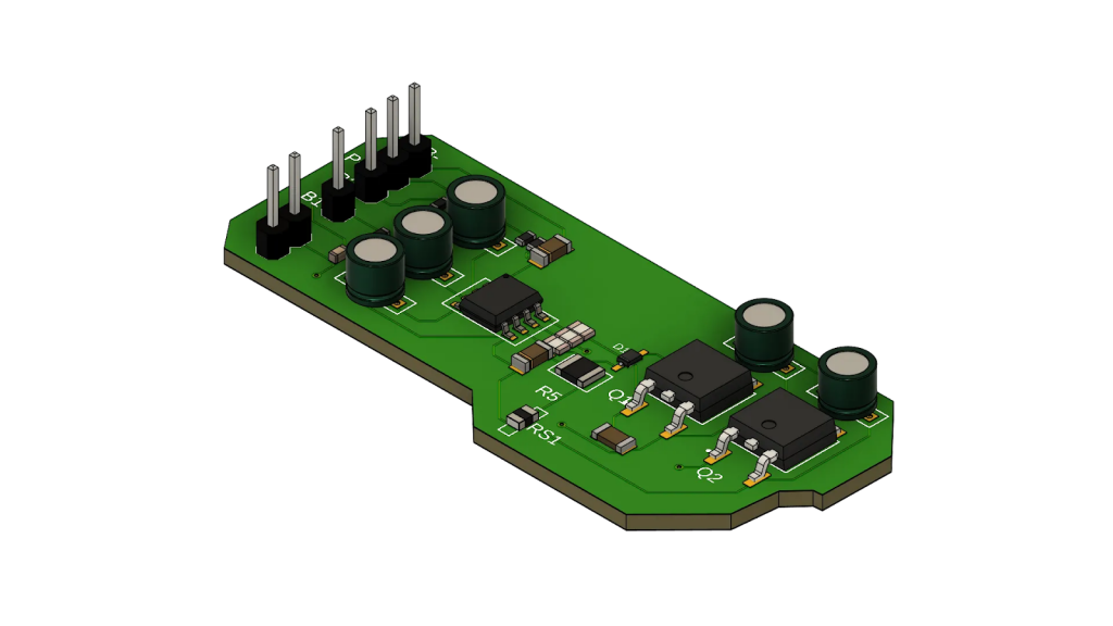
This week I kept working on the PCB. I have started making the schematic from last week in OrCAD, and looked through the pin assignment table in order to get an overview over what pins we have available and how to organize the board layout.
Robin :
After reviewing the datasheet, I conclude that I must have: VDD = 12.00 V, VC1 = 4.00 V, VC2 = 8.00 V, VC3 = 12.00 V
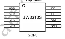
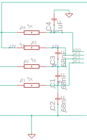
The values are good, so I’m moving on to the PCB.
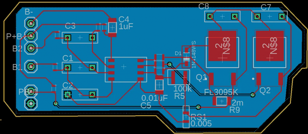
We also do the collision check (or verification) between the components.
Théo:
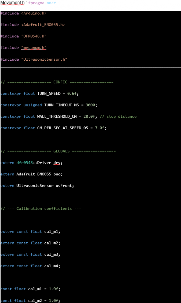
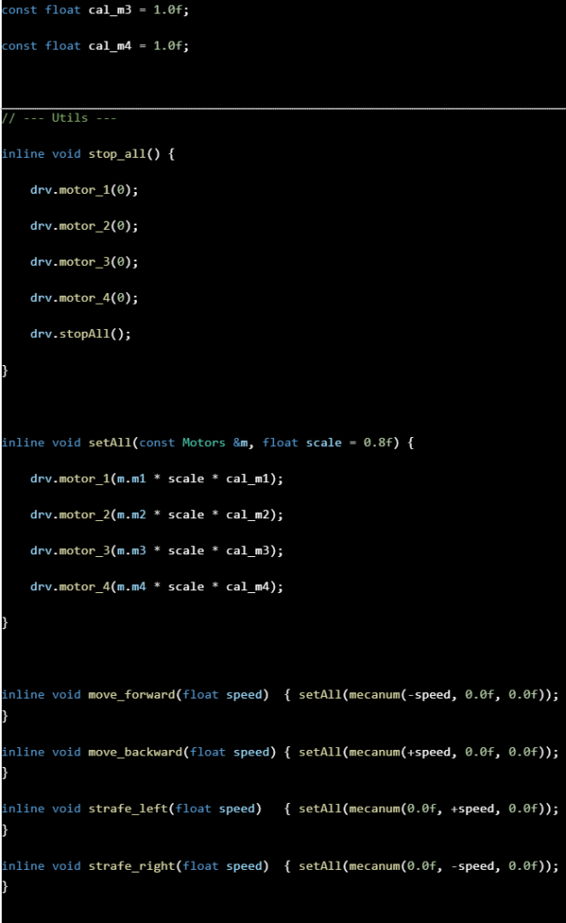
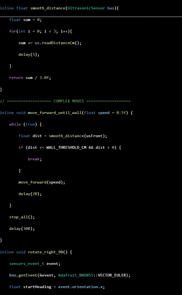
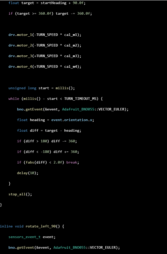
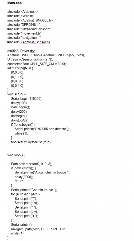
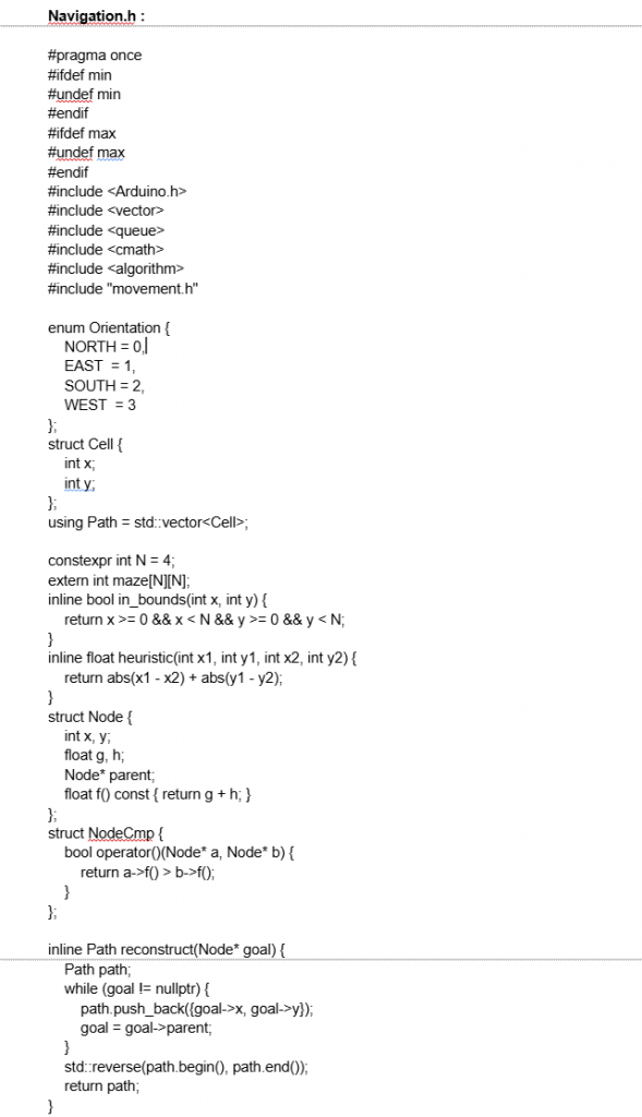
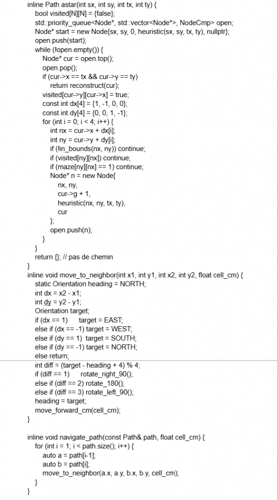
This week I was able to test the algorithm and it works in a square maze, as long as I give it the coordinates of its starting point and its destination. In the end, the issue I had last week had nothing to do with what Sondre was working on — it was caused by a poor file architecture and my IMU connection, which prevented the algorithm from actually running. For now, the car calculates a route and then follows it based on a matrix that represents the maze. I also created a movement module to improve and simplify my understanding of the motions and how the motors are used. What I will try to implement next week is enabling the car to calculate its route without knowing the position of obstacles beforehand, and if it encounters an obstacle, to recalculate its route accordingly. I should also improve the movement system to make its execution more precise, which will help increase the accuracy of the maze solving.
Matias:
This week we received the quotation from JLC, but the price was much higher than we expected. After discussing it with Steven, we decided that it would be more realistic to move forward with a protoboard version instead of manufacturing the full PCB.
My current plan is to use two pre-built L298 modules for the motor drivers, and then integrate the active filters and the step-down regulator myself on the protoboard. This approach significantly reduces the number of components we need to order and cuts down the assembly time, which is getting a bit tight.
Even though it’s not the original plan, this solution keeps the project moving forward efficiently and still allows us to test all the functionality we need. Next week I’ll start assembling everything on the protoboard and make sure the layout remains clean and functional