Our project consists in a game console based on Raspberry Pi and Arduino Mega which can run multiple games. The first main goals for this project were the following:
- Run one game with one player.
- Associate LEDs and sounds with the game.
- Multiplayer game.
- Multiple games.
- Menu to choose them.
Materials
For the project we used the following materials:
- Raspberry Pi
- Arduino Mega
- Custom PCB (Printed Circuit Board)
- Buttons x7
- Joysticks x2
- RGB LEDs x6
- Breadboard
- Screen & Speakers
Operating System
To run the Raspberry and to manage the emulators we chose a distro from Raspbian, PiMame which allowed us to have all the emulators that appear in the previous link (Mame, PlayStation, GameBoy, etc) . Besides that, it offers us other functions like reboot the console or shutdown, those features are really useful because we don’t need any keyboard to control the arcade machine. For that reason, only with the buttons of the controller its enough to manage the system. Another important feature of this OS that took us to choose it is because it lets us upload games via FTP.
Communicattion
1. PCB and Raspberry Pi (GPIO)
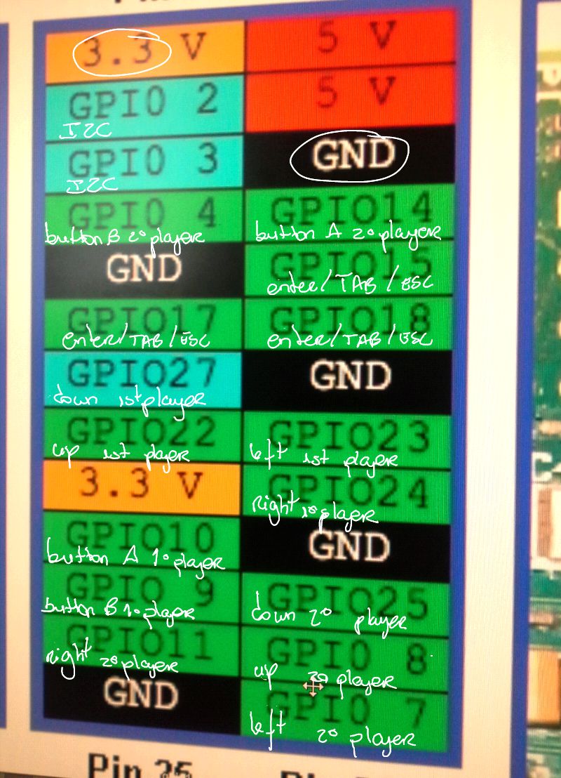
To manage buttons and the joysticks movements that we gathered from the PCB we used GPIO communication. In that way we used all the avaliable GPIO inputs on the RPi but 2 of them are used for the I2C communication between the RPi and Arduino. We used GPIO for the controls to avoid delays and other problems that could affect the perfomance of the game. Moreover, the number of inputs was enough for the controls we disposed.
2. Raspberry Pi and Arduino Mega (I2C)
We used this communication protocol to handle the transference of information from RPi to Arduino. RPi works like the master and Arduino like the slave. Due to we already had a modifed Arduino Mega (working on 3.3 V) we didn’t need resistors between the SDA (Data) and SCL (Clock) wires that connect both devices, because they work with the same voltage.
When the user presses the button A from the player 1 or 2, RPi send via I2C to Arduino an order to blink the LEDs with the red color.
Controller and LEDs
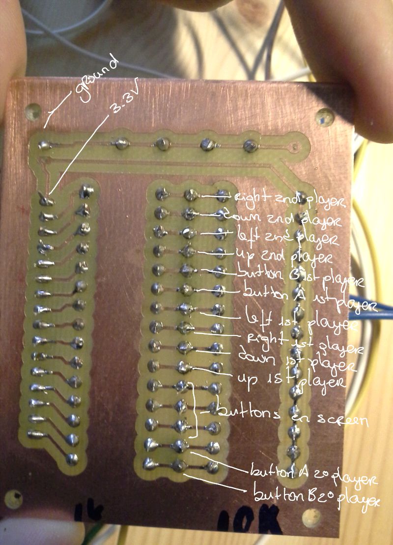
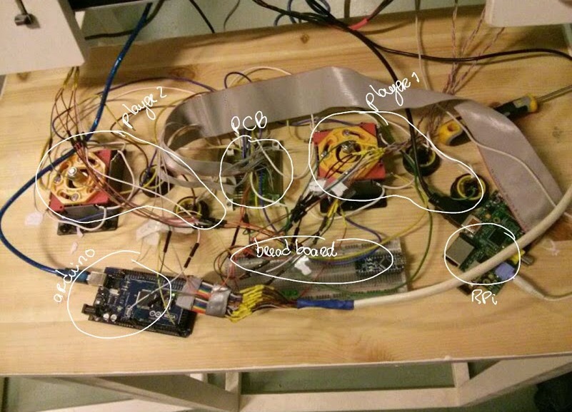
We have a main controller where each one of the 2 players has a joystick and two buttons (A and B). Apart from that, we have 3 additionals buttons next to the screen for the general commands (Select/Enter, Configuration/Tab, Exit/Escape). All these inputs go to the same PCB, but we used the breadboard to have additional grounds and voltages.
The PCB works with pull up/down resistors. The GPIO pins require pull-up resistors to 3V3 of 10k Ohm, and the switches pull down. Another 1K resistor in serial with the pin was added for protection.
The LEDS are managed by Arduino. When the player is not pressing the special buttons, the LEDS are doing a color wave and when he presses the button A from the P1 or P2, all of them blink at the same time with the red color, due to the I2C.
Raspberry Pi
To emulate the behaviour of the keyboard in order to play, we modified a program (pikeyd) that polls all the GPIO inputs and returns the value of each of them. We made the key mapping in order to have all the keys that we needed for the games. The advantage of this method is that we can play like if we were playing with our own keyboard. So, we don’t have problems with multiple keys pressed, delays, etc. This program works like a daemon at boot with root privileges.
Each emulator has his owns configuration files for the controls, which are going to be specified in the user manual. Either way, the user can modify the controls of all the games of all the emulators without needing a keyboard.
In addition, we have a script in Python working at the background at boot for the I2C communication. This script checks each 0,05 seconds if one of the special buttons (A) are pressed to send the signal to Arduino.
Arduino
The Arduino program controls the LEDs and the variable resistors from the screen board. By default, it is making a color wave with the LEDs and when it receives the appropriate signal from RPi, it changes the color of the LEDs to Red/Black to blink.
Moreover, it checks 2 variables resistors, one for the 3 left LEDs and the other one for the other 3 on the right. The consequences of the values of the resistors are the following:
- Over 500 (Half of the maximum value) -> Show the color wave and the red blink.
- Between 100 and 500 -> Show only the red blink
- Under 100 -> The LEDs are off.
Update: In a few hours, we will upload the main files we coded for RPi and Arduino as well as the User Manual.