Hello and welcome back!👋
This week has brought steady progress across both the mechanical and software sides of Hydrawlics, and everyone has been pushing hard as we move closer to the end of the project🤩
Below you’ll find a summary of what each team member has been working on!
Fredrik:
As we are nearing the end of the project, I realize that we have our work cut out for us. Still, it is motivating to see how far we have come, and the full hydraulic test last week demonstrated that the system works. The main focus from the mechanical side now is to reduce leakage from the hydraulic components, that being the cylinders, manifolds and valves.
Due to limited time I have not been able to work as much as I would want to with the sealing of the cylinder this week. I have however begun to brainstorm possible solutions. Unfortunately it seems like I wont be able to get around making new cylinders, but this gives me the opportunity to revise the design. I have been thinking about using TPU filament for sealing, as this is a rubber-like material that I can 3d-print. I have not worked with TPU before, so it is difficult for me to say whether this will work or not, but it might be worth a shot. This would mean we could drop much of the external components that I have designed my system around, giving me more freedom in design.
If TPU does not seal as well as I might hope, which could very well be the case, then the other option is pretty straight forward. We add more o-rings to the system. For the cylinders in the hydraulic test, we did not have enough o-rings for what we wanted, so I ended up only having the “critical” ones. This might have been a contributor to how wet our test ended up being. Especially the interface between the pvc pipe and the piston acted like a fountain. So if I can get ahold of the required o-rings, and implement another one in the interface between the pvc pipe and the piston, then I think we might be good.
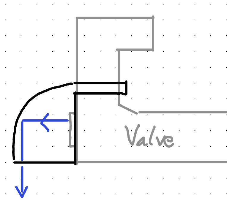
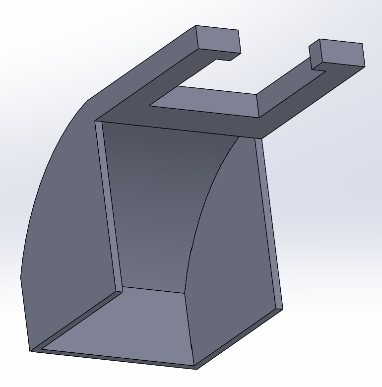
One of the larger causes of leakage was something slightly unexpected. Water was shooting out the side of the valve when direction of waterflow was changed. This is likely due to the fact that the valves are pneumatic, and not hydraulic. Other than that the valve works fine for our use, but it is definitely a problem. I have designed chutes that clamp onto the the side of the valve, to direct the flow of the water downwards, so that we at least can have some control of where it is going.
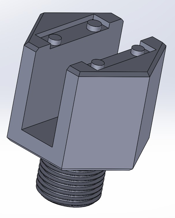
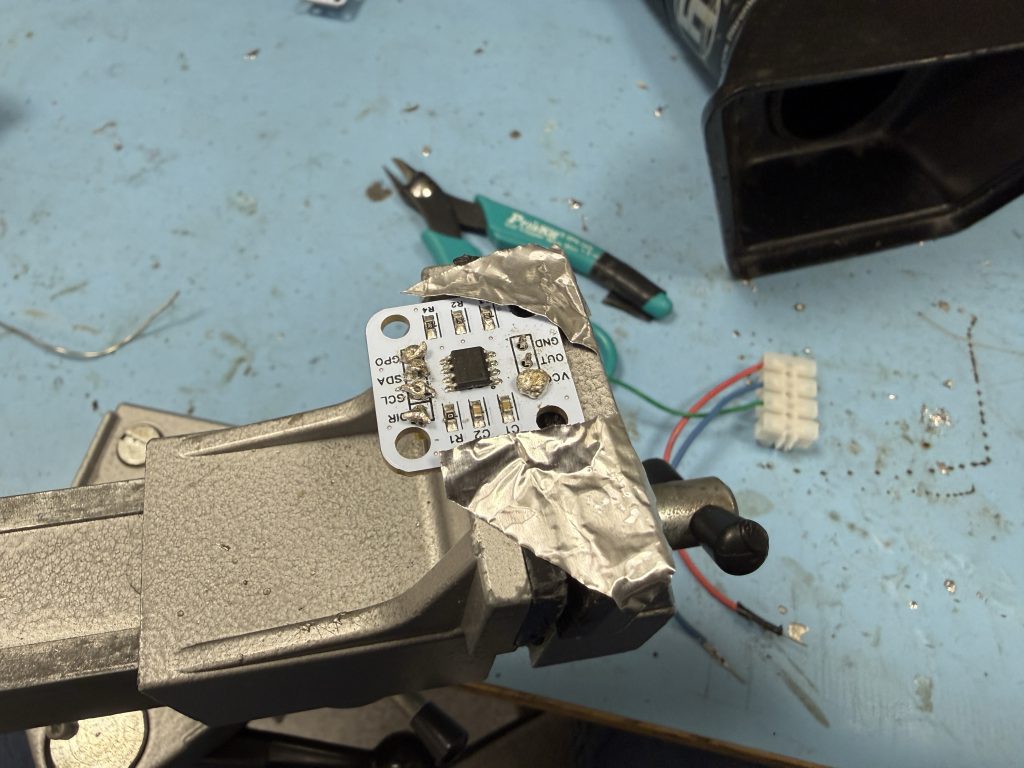
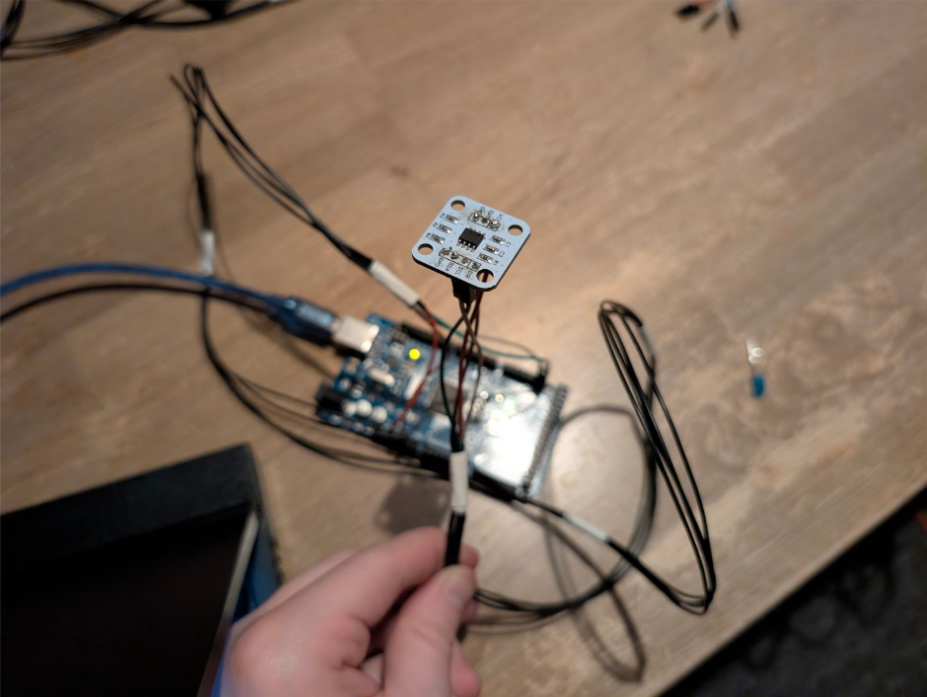
A part of the interface between mechanical and software is the angle sensing system that will measure the rotation in the joints. How these are implemented on the software side you can read about in Lisa’s part of the post. From the mechanical side it was difficult to implement them in the existing joint system. The sensor and the magnet both needed to be located in the center of rotation, and with at most a couple of millimeters between them. I decided to have them mounted at the far end of the joint, mostly making design changes to the bolt. This allowed me to keep the joint design for the most part unchanged. Since the sensors does not have the highest of production quality, it was a hassle to map out the design the board. The holes were of different sizes, and none were in line with each other.
For the angle sensing system to work, the sensor and the magnet need to be attached to separate arm segments. Due to the design of the joint, I can attach the sensor to the bolt, and the magnet to the bushing between the segments. The bolt houses the sensor, and have room for cables underneath. I will redesign the bushing to be two components that lock into each other, where one of them can be installed when the bolt is already in place.
Lisa:
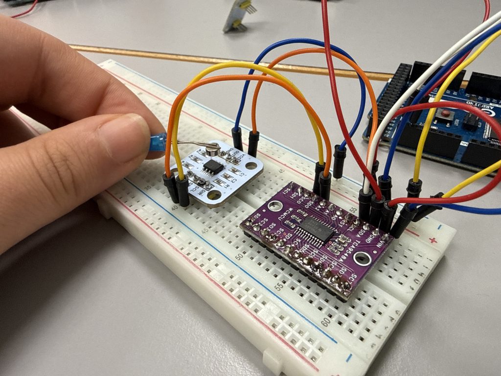
This week, the focus has been on upgrading our angle-sensing system. Syver had ordered new white sensor board, a AS5600 magnetic rotary encoders, which will replace the potentiometers that we’ve been using up until now. This upgrade is important for both the software as well as for the mechanical teams. The encoder provides more stable and precise angle measurements and it will also be easier to mount into the physical setup.
Before we could begin testing, we needed to solder all the components together. The whole software team; Emory, Syver and I spent quite bit of time getting everything prepared.
That meant attaching the header pins and the cable connector, and since this was my first time soldering something like this, it took a little while to understand everything and how the solder behaved. Once I got used to it, the process felt much more intuitive, though it was a bit time-consuming.. In the end, we managed to solder everything neatly, and the sensor board was ready.
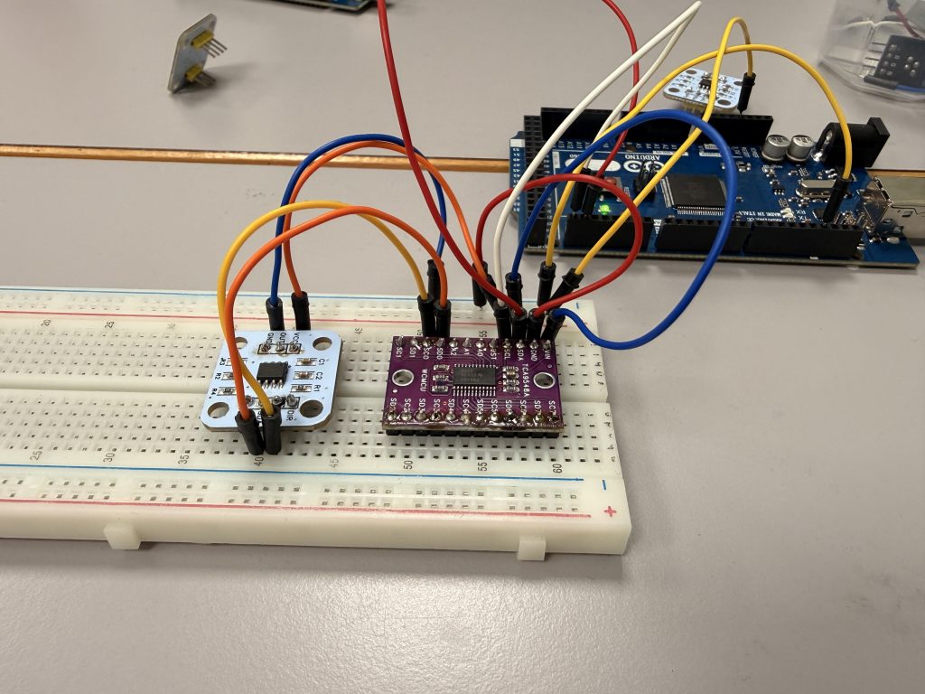
With the hardware prepared, the next focus was wiring the sensor through the TCA9548A I²C multiplexer, which is the purple board in the setup. Since we plan to use multiple AS5600 sensors in the system, the multiplexer allows us to select one sensor at a time by switching channels, which prevents I²C address conflicts. Once everything was connected, we loaded a small test sketch to verify that communication worked correctly, and it did!
For the test, we used a code snippet that selects channel 0 on the multiplexer and reads the 12-bit raw angle value from the AS5600. The sensor supports a full 0–360°rotation, something our previous potentiometer setup couldn’t reliably achieve, since normal potentiometers are mechanically limited to around 270° and would lose position information outside that range. The serial monitor from our test shows both the raw 12-bit value and the converted angle in degrees, making it easy to see how the sensor responds in real time. Holding a magnet over the chip immediately showed smooth angle changes, confirming that the sensor and multiplexer setup worked as intended.
Now that our new angle-sensing system is fully operational, the next step will be to integrate with the rest of our software setup for the hydraulic arm. Once this is done, the AS5600 will replace the potentiometer system entirely and it will give us a much more reliable and accurate foundation for tracking the joint angles across the whole setup.
Syver:
Hello! Last week, I completed the spatial logic needed for the control system to correctly draw on a plane. This week, we’ve continued integrating and testing the computer subsystems. I’ve mainly been focusing on the comms between RPi and Arduino, as well as some electronics work.
In week 7 I wrote about the interface between the Arduino and RPi while establishing a basic form of communications between the two. Amongst general definitions, we established that the Arduino’s memory could not afford to hold the whole instruction set that makes up an image. This meant that we needed a buffering system, which is what we implemented this week.
This was mainly a joint effort between Emory and me. First, we established the protocol. Initially, we defined packets as a batch of multiple GCode commands, with the Arduino receiving up to 10 lines at a time. We realized that this wasn’t necessary, so we decided it was best for the Arduino to respond after each line. The Arduino has three words in its vocabulary; “OK”, “Ready” and “ERR”. “OK” serves as an acknowledgement after each GCode line received with an accompanying simple XOR-checksum (e.g. “OK 53”). If the Arduino’s local cache is holding less than 10 instructions, it follows the ACK with a “Ready”, signalling the Python script to send one more line. This simple logic made the protocol easier to implement and debug.
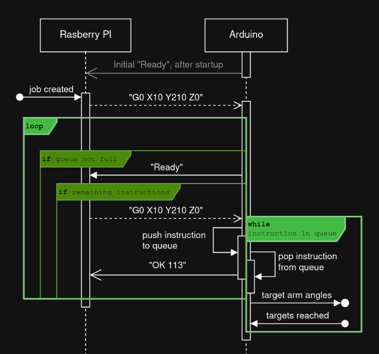
I worked on the Arduino side of the communications. It was implemented using some conditional logic in the main loop. Each iteration starts with checking if we have enough space to request data from the RPi by sending a “Ready”. Then, if there is content available in the buffer, the first line is extracted and sent to the ArmController class for parsing, updating its state if needed. The result is returned to the main function. If there the result is a new command, we add it to the command queue. If everything goes smoothly, the checksum of this line is replied to the RPi along with “OK”.
In addition to the communication implementation, I did some cleaning around the project; placing consts where I could and moving functions around to make it more readable. Most of my work this week on the kinematics repository can be seen in this pull request; https://github.com/7RST1/hydrawlics-kinematics/pull/7
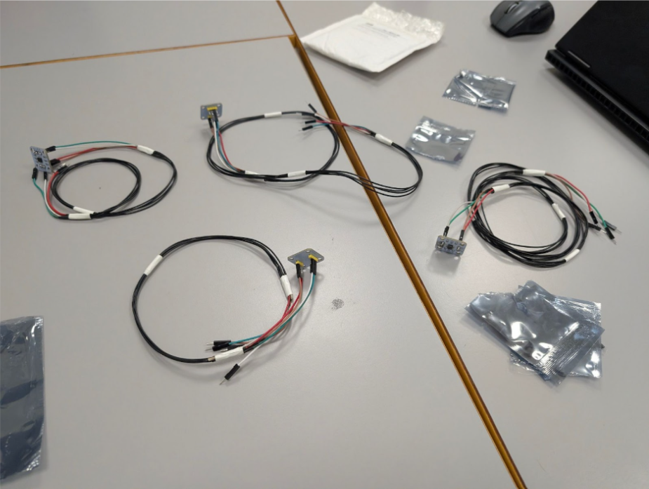
Since we are approaching integration, we needed to solder together the different sensors needed for the arm. Me, Lisa and Emory tried soldering header pins to the rotary encoders for each joint. We realized very quickly that this would be impossible without flux, so I ordered some before completing the soldering for the boards.
We also needed four long cables for each of the four rotary encoders, so we soldered them up as well by cutting male-female breadboard cables in half and adding a fitting amount of cable in the middle. After getting home, I continued working on the cables, adding heat shrink and grouping them. I am very happy with the results! Looks very industrial.
Once everything was soldered, I realized that resistance might be an issue. The sensor in the furthermost joint has 1m cables and they showed 1.3Ohm. Fortunately, since the nominal current through the rotary encoder is only ~6mA, the voltage drop is only about 15mV across the cables in total. I connected it up for testing, and luckily it worked well!
Everything is coming together well! Next week will see much cooperation with the other team members as we put the subsystems together.
Emory:
This week, I tried some soldering for the first time on a circuit board. It was fun, but it didn’t stick too well, as we didn’t have flux when I tried it.
After this, I worked on fixing the data flow that will transfer data from the Raspberry Pi to the Arduino, allowing us to generate G-code from an image and send it to the arm for movement.
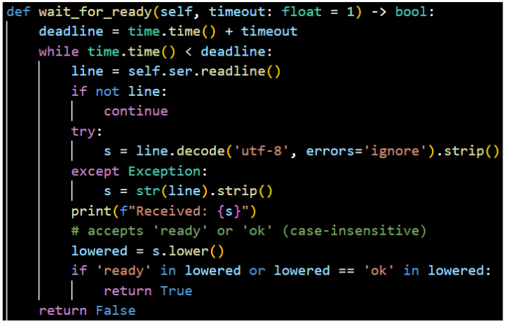
For the G-code to be able to be used, I had to make sure they only get sent when the Arduino sends a ready signal to be able to get them and not before, as then you would lose some coordinates if it’s not ready for them, and then you would not get a finished image. So, for that, I added a wait_for_ready function:
After that, I fixed the send_gcode function to make use of this and to have a wait time in case it takes some time for the ready signal to get through. The code checks for the ok/ready signal from the Arduino before sending every line of G-code. It also has a timeout that is way bigger than it has to be, at 2 minutes, to make sure it doesn’t disconnect too early. We expect it not to go over this time while sending over the G-code.
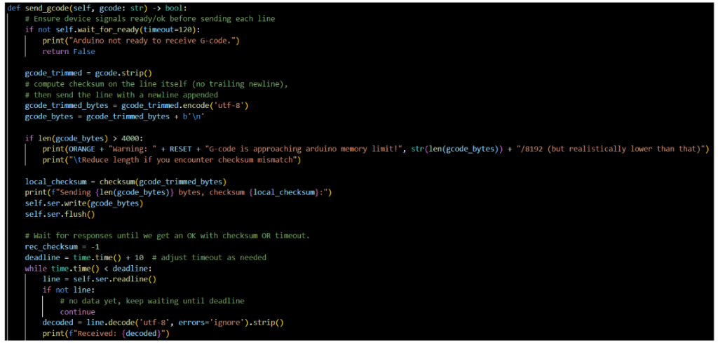
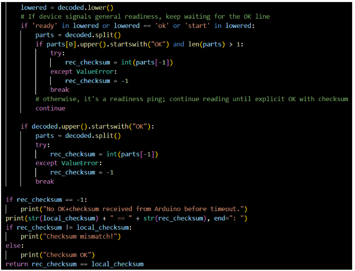
After getting an ok/ready signal, the G-code will start being sent, and before each line gets sent, it will check for a checksum that gets sent from the Arduino and compare it to a checksum the Python generates. When these two match, it will send a line of code before it again checks for ok/ready signal and the checksum. It will keep doing this until the entire G-code is sent.
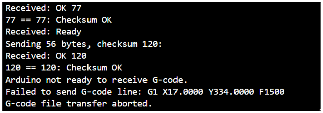
The snippet above shows some of the output the code gives upon receiving the ready signal and checking if the checksums match. The last three lines show what happens when the timeout is reached.
It was fun getting to try some soldering and do want to do that some more and get better at it.
Erling:
This week i have made massive progress! it may not look like a lot, but i have tears and suffering into the project, so i must go on. Even though a most of the courses have concluded instruction for the semester, there is a lot of work to do, and i would like about 15 more hours in a day.
i designed a solution for clamping on the small 4mm hoses in order to mitigate the leaking. I spent a while modeling these, and am reasonably sure they would work.
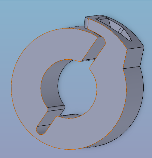
However, i overestimated the detail i can print with on my 3d printer. and after slicing and printing, i realized that there was absolutely no hope for the gaps i had modeled in the part to be printable. and as such, all the work i had put into it was wasted.
This was demotivating, and i focused on Product development for a while.
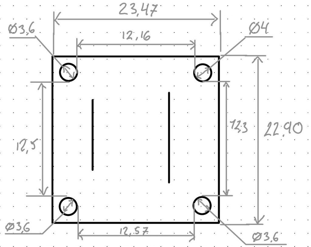
After some time i had the remarkable opportunity to aid my good friends in the software department who needed a container for the electronics of the system. They needed a case to house the computers and breadboards so that we can avoid making a huge mess of untraceable wiring and short circuit risks. I embarked on this mission with fervor, and set out time to fix my second 3d printer at home, so that i could tandem 3d print a lot of parts at the same time.
I modeled up the electronics box and a lid with vent holes/handgrabs, and put it all into the slicer for print. combined printing time for the parts was about 8 hours, and used about 500g of PLA filament.
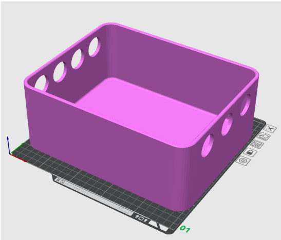
here is the electronics box, in all its glory, and beautiful color choice. Made on request specially for Syver.
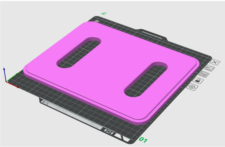
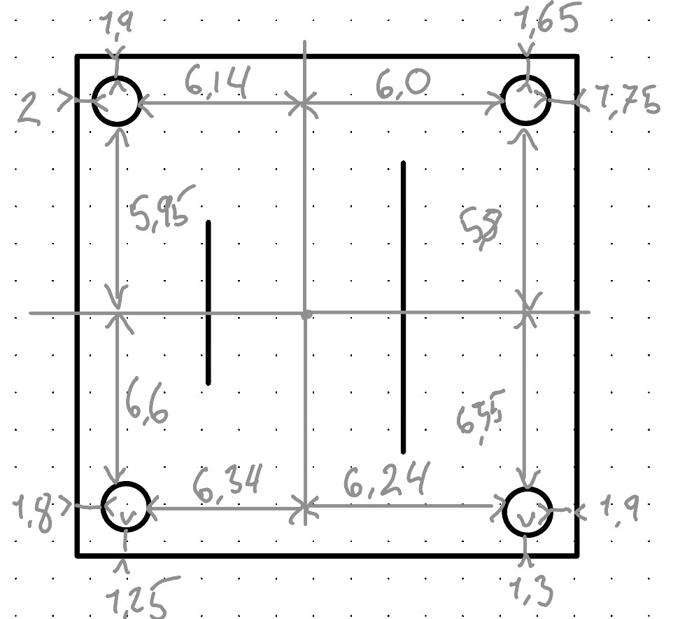
This is the matching lid, complete with a locating lip, and handgrabs / vent holes for the electronics.
My mission and work as a part of the software / electronics team helps us keep everything clean, and allows us to keep testing and implementing features and systems in a better, more approachable way.
This has been my contribution this week. See you next week!
That’s all for now, see you next week!