Mohammed A:
I focused primerly on fixing and addapting the middel section of the motorbike with the new components that will be implemented to the motorbike. I have figured out that the bike will be stretched in the longer side, and that the momntum wheel should have enough space to rotete and enough space for the bolts and nuts to be connected to the wheel with extra weight and make sure that it won’t colide with the bike. Doing further more reaserch and doing some analysis on the motor and I found out the the stable platfrom that the motor will stand on and with extra weight can break the extended platform that the motor is standing on. My primerly work is consentrated for now on the middel part of the motorbike, but still consider the thought of how to implent hob wheels (tron wheels) and servo motor to the bike without making it look clunky.
Salim:
I’ve been sick this week. Therefore, I was not able to attend in person.
I’ve mainly been working on the IMU sensor — step 2 and 3 from the last blog.
step 2:
The IMU sensor sends data that tells us the motorcycle’s angle.
It consists of a gyroscope and an accelerometer.
Before the IMU can be used, I need to calibrate it and determine its zero point — that is, the position when the motorcycle is standing upright.
I start by reading the IMU sensor values while the motorcycle is stationary.
Then, I find the difference between the motorcycle’s zero point and the IMU’s zero point. This difference is the offset.
When reading from the sensor, this offset is subtracted manually.
This gives the IMU a zero point that matches the motorcycle’s upright position, which is critical for the next steps.
step 3:
Once the correct zero point is found, I use data from the accelerometer and gyroscope to determine how much the motorcycle tilts to the sides.
These two sensors are used together in modern systems to determine orientation.
The accelerometer tells how far the motorcycle is from the ground. It’s stable but becomes noisy when the motorcycle vibrates, causing inaccurate readings.
The gyroscope tells how fast the motorcycle is tilting — the rate of angular change. Over time, it drifts and becomes inaccurate.
By combining both with a complementary filter, they correct each other’s weaknesses.
The angle is calculated:
Angle = α (previous angle + gyro rate * delta t) + (1- α) * accelerometer angle
Where the terms are:
- previous_angle – the angle measured in the previous step
- gyro_change – the change in angle measured by the gyroscope
- accel_angle – the angle measured by the accelerometer
- α (alpha) – how much of the gyroscope data to trust (0–1, where 1 = 100% gyroscope)
- This angle value will be used by the PID controller to control the balancing wheel.
The first part of the code:
// sette opp elektroniske koblinger
// støtte for imus sensor(bibliotek)
float angleNOW, gyroChange, angle;
float offset = 0; //JUSTER
float a = 0.9; // JUSTER
unsigned long time;
void setup() {
imu.initialize();
Serial.println(“Hold motorsykkelen, for å kalibrere”);
delay(2000);
// finne nulpunkt
int sum = 0;
for (int i = 0; i < 100; i++) {
sum += imu.getRotationX/Y/Z(); // test
delay(50);
}
offset = sum / 100;
Serial.print(“Offset: “);
Serial.println(offset);
time = millis();
}
void loop() {
// IMU reads raw data
int16_t accX, accY, accZ, gyroX, gyroY, gyroZ;
imu.getMotion6(&accX, &accY, &accZ, &gyroX, &gyroY, &gyroZ);
// last check
float lastCh = (millis() – time) / 1000.0;
time = millis();
// akselerometer: sjekk for acc x,y og z. test
angleNow = atan2(accX, accZ) * 180 / PI; //JUSTER
// gyroskop: teste følsom heten til motorsykkelen, med 65,5 og 32.8
gyroChange = (gyroY – offset) / 131.0;
// gyro + akselerometer
angle = a * (angle + gyroChange * lastCh) + (1 – a) * angleNow;
// Angle
Serial.print(“Angle: “);
Serial.println(angle);
}
Things I still need to test:
- Verify that the angle direction is correct
- Adjust which axis from the accelerometer is used
- Fine-tune the offset calibration
- Adjust how much of the gyroscope data (α) is used in the filter
Next week, I will test this together with the rest of Muhammed Ø’s code, and perform physical testing on the motorcycle.
Muhammed Ø:
I was going to add this part to last weeks blog post but I didn’t have time to add it in therefore I am adding it to this weeks blog post.
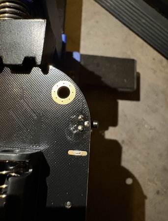
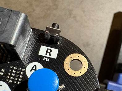
We had broken one of the buttons on the BitPlayer for the micro:bit microcontroller, as shown in the pictures below.
when we would hold the button in place and try to use it we noticed that it would work sometimes, which means that the pins from the button is sticking enough out to have a connection with the board, which made me attempt to repair it.
I first heated the solder which is already on the board while pressing the button in place, this allowed the solder to flow and get attached back to the button. After which I added more solder to the pins that were sticking out of the back. The button was attached nicely and was working as intended. Unfortunately, my friend who was helping me accidentally dropped the controller, which made the button brake off again, and the second time I tried to re attach the button it wasn’t as good as the first, but it was still working.
This week I focused on the step four and step five for implementing the self-balancing element of the motorcycle.
We have chosen moderate values for the X values of the PID algorithm, this is something that will potentially be changed when we test the code next week depending on how the system acts. The X values are as follows: X1: 25, X2: 0.9 and X3: 1.4. in the code I wrote one function responsible for setting the motor speed based on the output from the PID, and this is the code:
// sette opp elektroniske koblinger
// støtte for imus sensor(bibliotek)
float X1 = 25.0;
float X2 = 0.9;
float X3 = 1.4;
int speed1 = 0;

int MotorENA = 9;
int MotorIN1 = 8;
int MotorIN2 = 7;


void setup() {
  pinMode(MotorENA, OUTPUT);
  pinMode(MotorIN1, OUTPUT);
  pinMode(MotorIN2, OUTPUT);
  Serial.begin(9600);
}

void setMotorSpeed(int speed) {
  if (speed >= 0) {
    // Fremover
    digitalWrite(MotorIN1, HIGH);
    digitalWrite(MotorIN2, LOW);
  } else {
    // Bakover
    digitalWrite(MotorIN1, LOW);
    digitalWrite(MotorIN2, HIGH);
    speed = -speed; // Gjør positiv for PWM
  }

  // Begrens hastighet til 0-255
  speed = constrain(speed, 0, 255);
  analogWrite(MotorENA, speed);
}

void loop() {
  // PID-lignende kontroller
  int pwm_s = -constrain(X1 * angle + X2 * gyroChange + X3 * -setMotorSpeed(speed1), -255, 255);
  speed1 = pmw_s;

  // Styr motoren
  setMotorSpeed(pwm_s);

  Serial.print(" | PWM: ");
  Serial.println(pwm_s);
}
Meron:
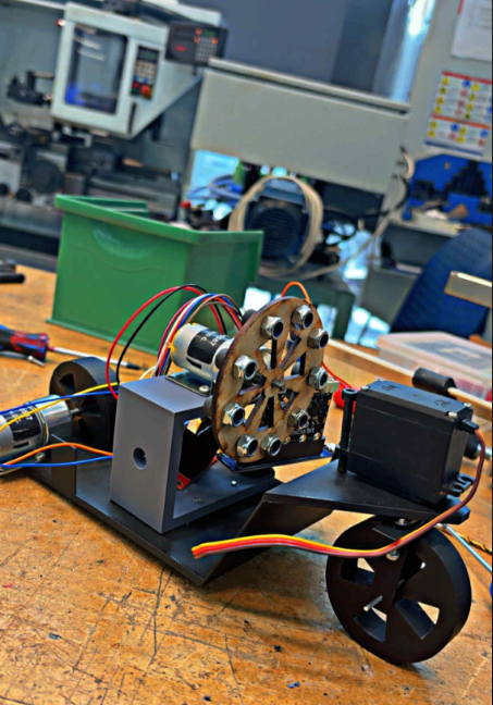
This week I was focused on the balancing system for our auto balancing motorcycle. I worked on creating different versions of balancing wheels with various diameters and sizes to test which one works best. After getting feedback from Rechard, I used the laser cutter instead of the 3Dprinter for some of the parts which gave more accurate and cleaner results.
I then assembled the balancing wheels and added screws on the top to give extra weight to help the wheel create better balance when it spins. The balancing system is now mounted in the middle section of the motorcycle allowing the motor to handle turning and movement smoothly. Like u see down in pictures Now the system is ready for testing to check how well it is balancing the motorcycle. There will be more testing, redesigning and printing in the coming weeks to improve the setup. The balancing wheel with rubber will be used in our final version of the motorcycle