Sondre:
This week was both fun and frustrating. I didn’t manage to solve everything I planned, partly because another course needed attention, but I still made solid progress.
The original sprint goal for these two weeks was to make the car navigate without touching the walls, which we actually finished earlier. Now that Theo is working on a maze-solving algorithm, my focus has shifted to making the car drive more smoothly through the path.
To improve stability, I’ve been combining the ultrasonic sensors and the IMU in a PID controller, and we also added motors with encoders as a backup in case the sensors give bad readings. Most of my time this week went into implementing these encoders.
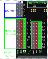
I first tried integrating Theo’s servo code, but ran into a pin conflict: the pins he used were the same ones I needed for ESP32 communication. Moving the servos wasn’t as simple as expected, since the ports use an external I2C driver, which would require bigger code changes. After wasting too much time on it, I put that issue on hold and will revisit it with Theo later.
Even though not everything got solved, the encoder setup is progressing well, and the car is getting closer to driving as reliably as we want.
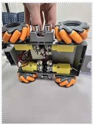
My next task was to install the new motors with encoders. We received some motors from Steven, but the encoder housing made them too large to fit in the chassis. Instead, I used the motors I bought earlier, which came without housings and had just enough space to fit, as shown below:
Next, I wired the encoders to the ESP32. Each motor has six wires: two for power to the motor, two for encoder signals, and two for encoder power. The signal wires went straight to the ESP32, while the 5V and ground were shared between the encoders, ESP32, and Micro:bit. For communication, the ESP32’s RX pin was connected to the Micro:bit’s TX pin, and vice versa.

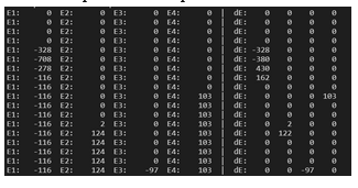
After wiring everything, I used ChatGPT to generate a test program for the ESP32 to check if it could read position and speed data from the encoders. The test worked, as shown below:
The next step was to send encoder data from the ESP32 to the Micro:bit. After updating the ESP32 code, I suddenly couldn’t upload anything—only error messages. I spent a long time troubleshooting (restarting the PC, switching USB ports, forcing boot mode, etc.), but the issue turned out to be simple: the RX and TX pins can’t be connected during upload because they create noise on the board. Disconnecting them fixed it instantly.
Then I tried writing the Micro:bit code to receive the data, but ran into another issue: the Micro:bit uses the mbed framework for UART, while we are coding in Arduino, which doesn’t include a working UART by default. I tried creating a manual UART instance and even a software UART, but nothing worked. So instead of UART, I switched to I²C communication. It’s slower, but much easier to implement—and it also solved the pin conflict with the servos.

After flashing the updated ESP32 code and switching the connection to I²C, I modified the Micro:bit code and ran a test. Data did come through in the terminal, but it was just unreadable gibberish.

And that’s where I had to stop for the week.
Anette:
This week I have been looking at the pins we need for the microcontroller and compared it to the ones we already have on the microbit. I also looked into how I was going to design the circuit. When looking at the datasheet I found different reference circuits that I could use as a basis for the design. The circuit below is the one I am going to look at due to this being the only one containing an antenna.
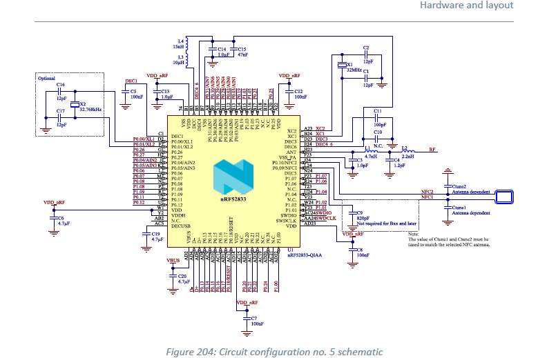
Having a reference circuit also helps because I will likely be unable to simulate the circuit in PSpice. This is due to there being no premade PSpice models for the NRF52833. It’s possible to make a custom model, but from my understanding this is a new and time-consuming process that I will not be able to finish in the limited time. I also started making a part library for the circuit so I can finally finish the design and proceed to the PCB itself. My goal is to finish the PCB before the end of next week at the latest, and I hope this is possible.
Matias:
This week I didn’t make a lot of progress on the design itself. I mainly focused on checking how to order the PCB and understanding the process and requirements for submission. I also sent the BOM (Bill of Materials) to Steven so he could review it and make sure everything is ready before placing the order.
It’s been a lighter week in terms of hands-on work, but an important step toward getting the board manufactured. Hopefully, next week we can move forward with the PCB order and start preparing for the next stage of the project.
Robin:
Here, after finding all the components, I was able to add them to my electronic design software, and here is the result.
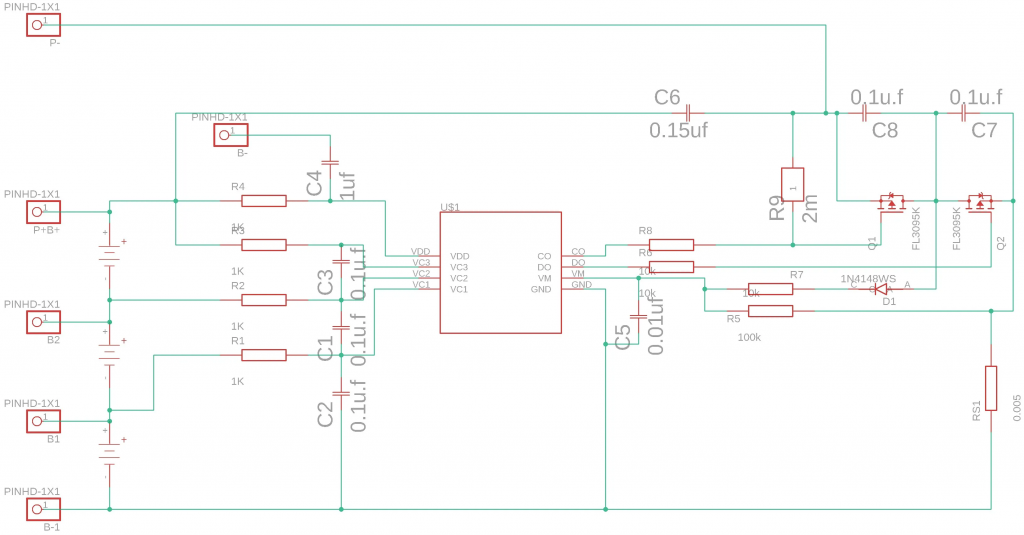
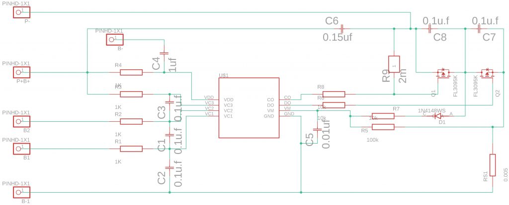
Here, after finding all the components, I was able to add them to my electronic design software, and here is the result.
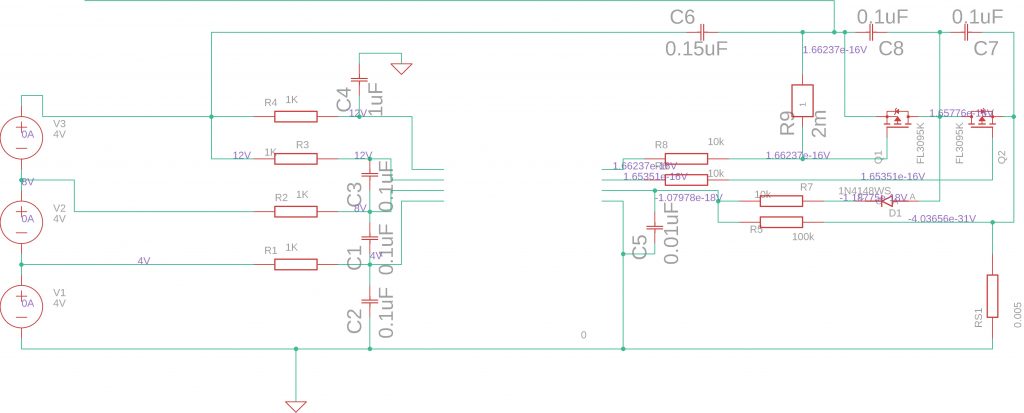
On the third schematic, I removed the central chip because it isn’t easily simulatable in SPICE, but I am simulating the rest of the schematic to see the values I have at the input and see what I get.
| Type | Name | Value |
|---|---|---|
| voltage | v(x_q2.1) | 1.657760795107259e-16 |
| current | i(e.x_q1.egd) | -6.277435765354723e-21 |
| current | i(e.x_q2.egd) | -8.579167147515032e-21 |
| voltage | v(n_1) | 8.000000000000000e+00 |
| voltage | v(n_2) | 4.000000000000000e+00 |
| voltage | v(n_3) | 1.200000000000000e+01 |
| voltage | v(n_4) | 1.200000000000000e+01 |
| voltage | v(n_5) | 4.000000000000000e+00 |
| voltage | v(n_7) | 1.200000000000000e+01 |
| voltage | v(n_8) | 1.657760795107270e-16 |
| voltage | v(n_9) | 8.000000000000000e+00 |
| voltage | v(n_10) | -1.079776969240537e-18 |
| voltage | v(n_11) | 1.662366746862610e-16 |
| voltage | v(n_12) | 1.653514107423402e-16 |
| voltage | v(n_13) | -1.187754666164550e-18 |
| voltage | v(n_14) | -4.036564748676257e-31 |
| voltage | v(n_15) | 1.653514107423402e-16 |
| voltage | v(n_16) | 1.662366746862610e-16 |
| voltage | v(n_17) | 1.662366746862610e-16 |
| current | i(v.x_q1.vfb) | 7.713284310313707e-31 |
| current | i(v.x_q2.vfb) | 4.484155085839415e-44 |
| current | i(v_v1) | 0.000000000000000e+00 |
| current | i(v_v2) | 0.000000000000000e+00 |
| current | i(v_v3) | 0.000000000000000e+00 |
| voltage | v(x_q1.1) | 1.657760795107269e-16 |
| voltage | v(x_q1.2) | 1.662366746862597e-16 |
| voltage | v(x_q1.3) | 1.662366746862610e-16 |
| voltage | v(x_q1.12) | 4.605951755327956e-19 |
| voltage | v(x_q1.13) | 3.138716013698980e-21 |
| voltage | v(x_q1.14) | 0.000000000000000e+00 |
| voltage | v(x_q1.15) | 4.574564557811399e-19 |
| voltage | v(x_q2.2) | 1.653514107423402e-16 |
| voltage | v(x_q2.3) | 1.079365239635769e-27 |
| voltage | v(x_q2.12) | -4.246687683857223e-19 |
| voltage | v(x_q2.13) | 4.289583628900372e-21 |
| voltage | v(x_q2.14) | 0.000000000000000e+00 |
| voltage | v(x_q2.15) | -4.289583519043370e-19 |
I’m not yet sure if these values are correct. I need to check the datasheet for the main component. These values:
- voltage v(n_1) 8.000000000000000e+00
- voltage v(n_2) 4.000000000000000e+00
- voltage v(n_3) 1.200000000000000e+01
- voltage v(n_4) 1.200000000000000e+01
…may not correspond to the main component.