Wang
This week our goal is to get 4 LEDs to light up depending on where I move the joystick. This week I also got the joystick that I’m actually going to use. I haven’t worked with it yet since I got it at the end of the week but at the end of the week I made my own joystick to see if I could get it to work.
What I managed to do was that the LEDs lit up and I got a readout on the serial monitor. But it looked like it was just random numbers so it didn’t have a real connection between them. The joystick I used was a KY-023.
This was my readout.
VENSTRE
X:    6, Y:  157
VENSTRE
X:    7, Y:  151
VENSTRE
X:    7, Y:  163
VENSTRE
X:    4, Y:  162
VENSTRE
X:    4, Y:  158
VENSTRE
X:    8, Y:  159
VENSTRE
X:    6, Y:  158
The real problems may have been that I have connected the wrong thing to what I had said what the pin was. Maybe the doctor read the schematic wrong or something.
Or maybe it is the code that is the problem that is most likely.
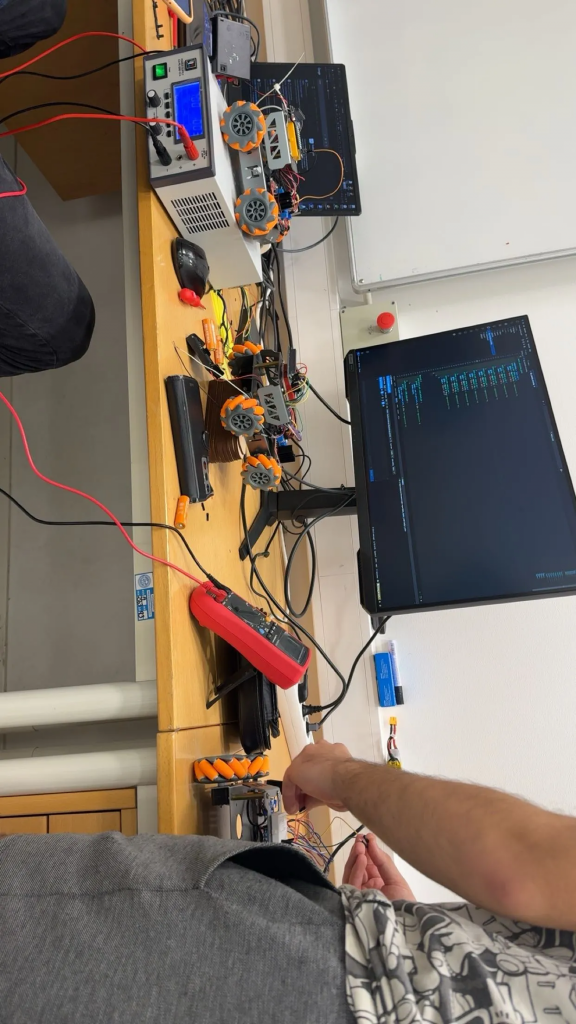
Here is also a picture from the week when steven and oske worked on figuring out a problem with the car we had.
Henning
This week has been a bit more research week on my part. Right now i was trying to make my code accessible towards the Raspberry pi. After some searching, i found out that i needed QtMqtt library. This was not in the “QT maintenance tool”, so i found a link towards GitHub:
I downloaded it as a Zip for now, but im struggling a bit to make it work manually with Qt. I will continue to push towards it through next week, if not i will look towards another solution.
My second unfinished point is the draw mazes still. Currently the AI draws different images each time i ask. Which is of course nice and everything, but every result is wrong. That comes from the issues in the main code on my end.
Issues still at hand:
- Make the connection point to the AI (get QtMqtt to work)
- Make the drawings of the mazes more accurate (draw the right paths)
These two issues seems to be the last stretch on my end of this project, so this should be doable for me given the time we have left.
Øivind
Week 12
-DISCLAIMER!!
- My last blogpost is not as it was supposed to be. It looks like a mess with the pictures of interest hidden and pictures that seems “way out”. I have sent a request to our “blogmaster” and asked if I should do anything different regarding formatting. I cringed when reading it myself) and I do not stand for such poor performance of my material. I hope this post gets embedded in the right way. You all missed a fun part of my blogpost that emphasized the struggle we all need to walk through.
Anyways we need to focus on the bright side!
Finally!
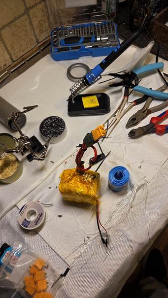
One piece fused 3s2p battery-pack with temperature sensor, strain relieved wires and XT60 connector ready to be shrink-wrapped!
The charger is ready, but the shrink wrap was terrible, so I need to find another solution to hold those parts together in a proper manner. The easy way would be LEGO or Velcro, and to spare time on details, I might do so. “Time will show” (ref: Sheik Ben Redic Fy Fazan)
I will use KAPLA (wood) as standoff for the DC converter and either implement a shunt and a current sensor or use a finished module to measure the charging and alert when the batteries are at desired potential. I have put it in a box which I mounted quick release hinges on. Next will be to include some logic and some form of monitoring unit. I think LED’s and buzzer as mentioned will suffice.
Next up, get a sense of what we try to do; locate lava tunnels, I consider using a small metal detector to simulate the cavity detected by a Ground penetrating radar. That way I can show that the Rover can find something beneath the surface. Then I can use the drill rig to drill through the surface and use a vacuum pump to collect “moon dust/regolith” or what else we might find.
I’ll check if Thingiverse.com has files I can use, there are lots of prefabricated drawings makers have made available for free.
Fusion gives me headache! It’s fun and all but, I need practice I can’t find time to implement. Thursday, I saw a drawing by one of the guys in my electronics class, which is on the Mini-Muck project and the drawing he made in Fusion was very impressive! I almost “Went on a Brink” (Google it if you are interested) by feeling inferior to that classmate.
Regarding our battery-pack, and why I use time on the safety-features; it’s nothing you want to deal with if it fails and catches fire. This is typically caused by thermal runaway which is a self-sustaining, rapid increase in temperature. This can be triggered by internal short circuits, damage, manufacturing defects, and overcharging, especially in poor-quality or aged batteries. Ours are brand new and well balanced! But safety first, always, and mind that when thermal runaway occurs, it can lead to explosions, violent bursting of cells, release of flammable gas, and intense fires. I do not want to be the one responsible for fire alarms and evacuation of USN and the affiliates.
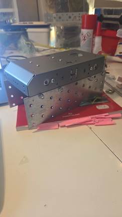
I had an AI to code a template for PID tuning for me. So, I need the Rover to get ready, so I can harvest data. While I first was considering weight on the Rover, I have now made it a Tank. But this was more of a test to visualize. I visited Biltema (ohhooo oh oooh!) yesterday and picked up some polycarbonate plates. But I walked past some metal parts, left the plastic and I went for the metal that is at a cheaper price (Cheaper Than Dirt, practically). So now I have a Tank.
But I have spoken to Richard by mail and in person today, and we have some plans. He suggests laser-cut wood, which is a better option if it is stiff enough to suppress too much unwanted vibrations
MATLAB plots (general) and a Tank:

Earlier I mentioned a metal detector to serve as a simulated GPR (Ground Penetrating Radar). I have one, but not the type I really desire. But it works OK. If it’s implemented, I will consider taking it apart to see how I can send the signal to the RPI. Another option is to use a microphone and filter the frequency of the sound to make the MCU fetch the signal. As you can see in the video, the quality of the metal detector isn’t better than it picks up it’s own signature when adjusting the sensitivity too high. Maybe I can overcome this in a way, if I “hack” it. It seems like it picks up signals through quite thick materials. I will test under different circumstance, so I (might) understand how this unit works.
https://vimeo.com/1134876497?fl=pl&fe=vl
After extensive trials by Oskaras (fellow member of our group) to read the temp sensor on our battery-pack, which led nowhere, I used a couple of hours to detect errors, and now it seems like the sensor is defective. I got help from C’-GPT, to build different codes for me (not my main domain, and Real-Time systems and other courses, have taught me that coding takes time!), also I regret wasting Oskaras time with troubleshooting a defective device. I will re-open our battery-pack, check the component once again, and beat myself over not checking the sensor before I used half a roll of Kapton tape and that useless shrink-wrap. Today is Saturday 08.11.25 and I wait for better casing for the battery-pack anyways which will make it more “stream-lined”, better looking and not so Reodor Felgen (my Hero) as it is right now. Anyways I considered doing this, because I have checked options of connecting JST-XH to the balance-leads and BMS to support charging on another charger if I have made other mistakes. Always safety first in this game.
If the sensor was DOA, I take the financial loss like a boss and might implement a digital one instead, unless I can grab another analog device somewhere.
I got readings all the way from -273.15 through 5-10, around 40 celsius and also NaN (Not a Number, often caused by dividing by zero (or other mathematical nonsense)).
Upcoming:
- Analog Temp/Digital Temp
- LEDs for charger
- Test sensors
- Chassis
- Solder perfboards/protoboards
- New motors?
- Talk with group about changing the wheels on the Rover
- Plan for surface (Moon surface mock regolith) to be drilled
- -Become a cross-disciplinary engineering expert-
“The only difference between men and boys, are the price of their toys.”
-Unknown
First or maybe second lesson in “Development of Smart Systems” Steven told me the use of pre-made, typical hobby RC-cars often used “heavy battery-packs, so we do not use them.”
I fell into a trap I made myself:
https://vimeo.com/1134915125?fl=pl&fe=vl
Zardasht
Troubleshooting Serial Communication Between Raspberry Pi and Arduino
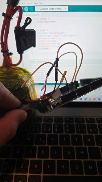
Over the past few days, I’ve been working on solving a frustrating issue with serial data transmission between my Raspberry Pi and Arduino. Things didn’t go as planned when I tried to read data correctly from the Pi to the Arduino. After some digging, I realized the root of the problem: voltage mismatch.
Voltage Mismatch: 3.3V vs 5V
The Raspberry Pi operates at 3.3V logic, while the Arduino uses 5V. This difference can cause unreliable communication or even damage components if not handled properly. Ideally, I would use a level shifter or resistors to adjust the voltage, but I didn’t have the necessary equipment on hand.
Manual Testing and a Temporary Fix
To work around the issue, I manually tested
the code by disconnecting the Arduino’s RX 0 (receive) pin. I ran the code on both the Raspberry Pi and Arduino separately, then reconnected the RX 0 pin. Surprisingly, this allowed the system to run normally—but it’s not a sustainable solution.
Exploring Alternatives: Micro:bit
While researching and, after speaking with Stiv, I received some useful suggestions about using the micro:bit as a potential solution., which also operates at 3.3V. This could be a promising alternative for my setup. I plan to test it with Oskar to see if the micro:bit can receive and interpret the data signal correctly.
Next Steps
If the micro:bit proves to be compatible, it might simplify my project and eliminate the need for voltage conversion. I’m excited to explore this further and will share updates as we test and refine the setup.
Oskaras
So for this week i set out to create a library for the motor controls that would also use the already existing pwm control library. The idea was that this would heavaliy simplify the main file, and instead of needing 12 lines of code just to command a state of the car i would just use a function spesifiyng the direction and speed persentage
link to the commit: https://github.com/OskeLTU/Zephyr_code/commit/9ded2297ca8ce5f43d7d3099d6009594a000e9e4
So again this code is not complete. I suspect that the issue is somewhere with the configuration. Regardless i did get the functions to connect to one another across files and did get some actual output on the wheels.
Apart from that on friday last week i helped with troubleshooting a temperatur sensor. As well as just trying to pick up an analog signal from it.
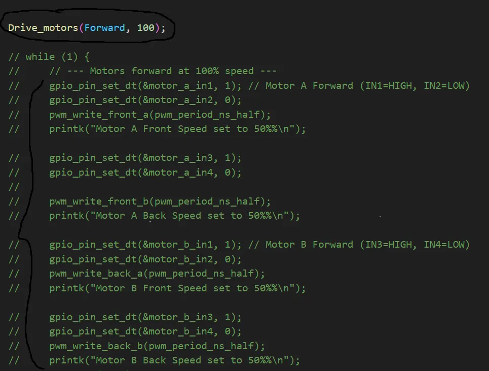
for refrance the libraries will compress the whole code that is green with just that one line. And there will also be a function to controll individual motors if that is wanted.