Hello and welcome back!👋
Our blog is a tad late this week. Many of our members had important obligations in other courses the previous weeks, so we had shorter time for preparation than we would like. But we are excited to show what we have been able to accomplish this week!
At the end of the blog post, we show the full hydraulic system test. Be sure to check it out!
Fredrik:
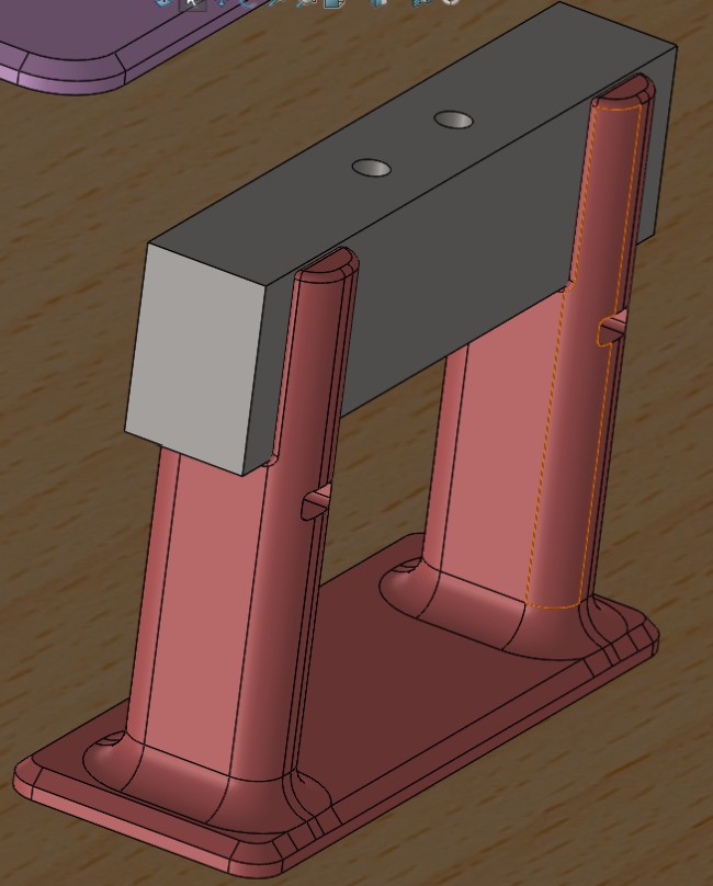
This week I had full focus on the full hydraulic system test, combining the mechanical and software parts of our project. There were still some parts missing, so my focus this week was filling these gaps. The missing parts included the cylinders, the cylinder mounts, and the remaining valve attachments.
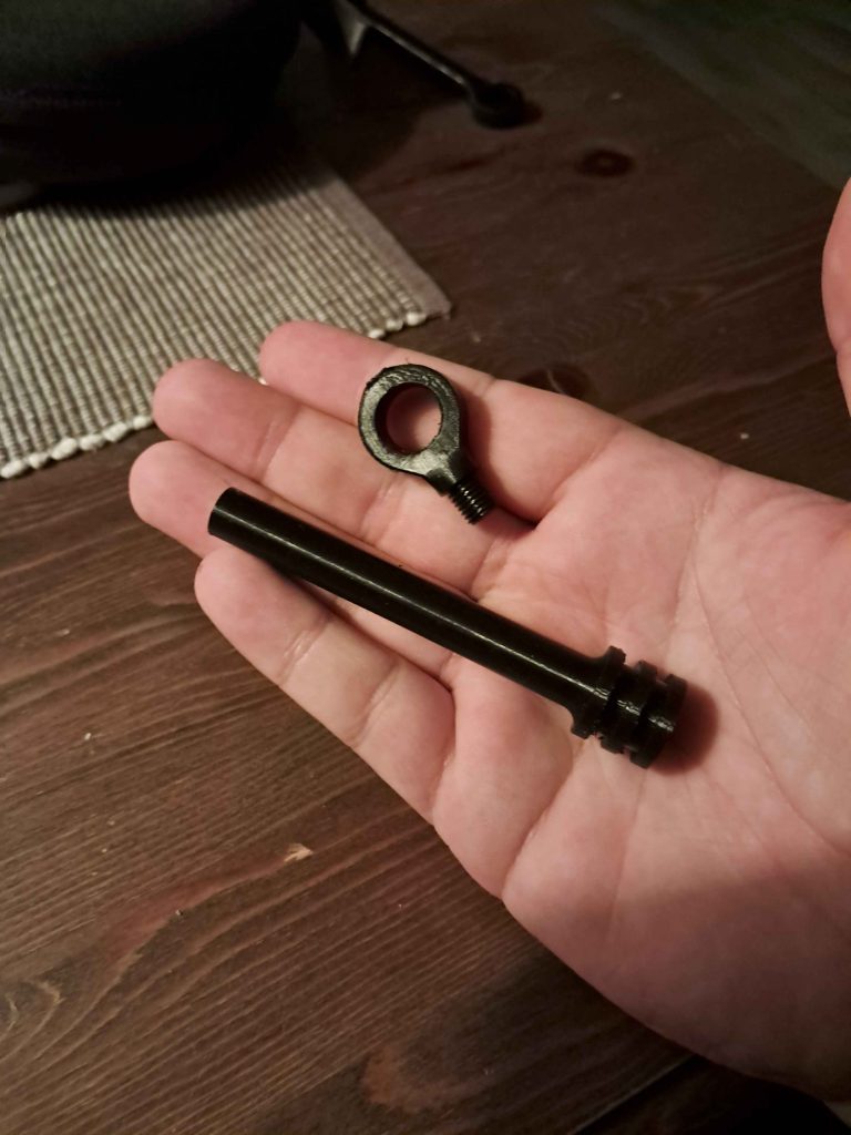
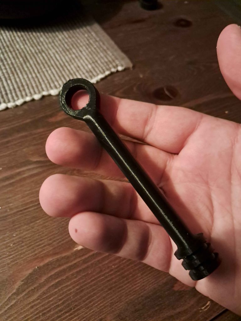
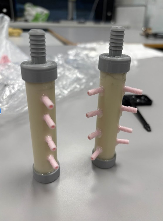
The cylinders were the most complex parts that I needed to make this week. The design was more or less complete from previous work, but some elements had to be changed. After printing the piston design from last week, I realized a somewhat obvious mistake, that being that I could not mount the piston to the end cap of the cylinder. Therefor I needed to split the piston from the attachment hook, while making sure I could attach it again without it loosening. Therefor I implemented a threaded connection, which ended up working perfectly.
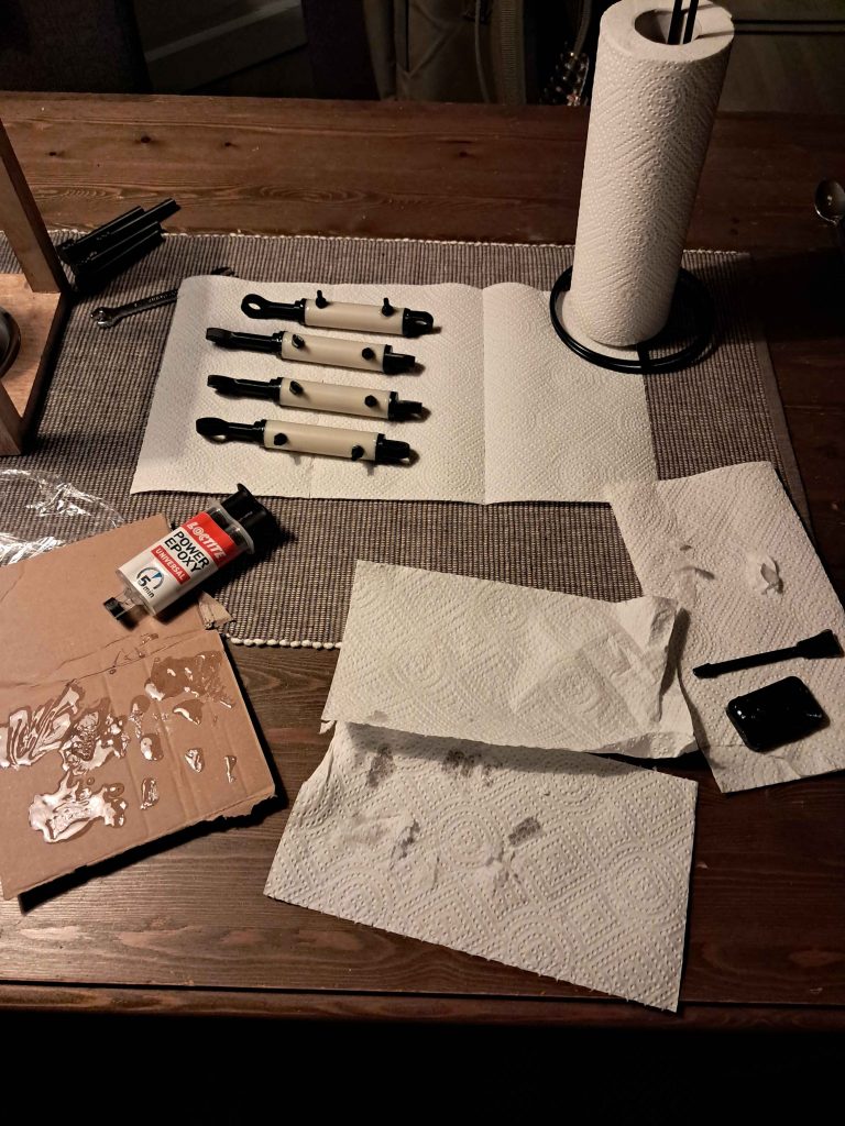
After all parts were ready, I mounted the o-ring on the cylinder end cap, and realized that the fit for the piston was way too loose. After another round of redesign, I got it to a place where I was comfortable testing it. Later during the test you can see that the fit is still too loose. I glued it all together using two component epoxy-glue, as this has good adhesion to petg and pvc, and is resistant to water
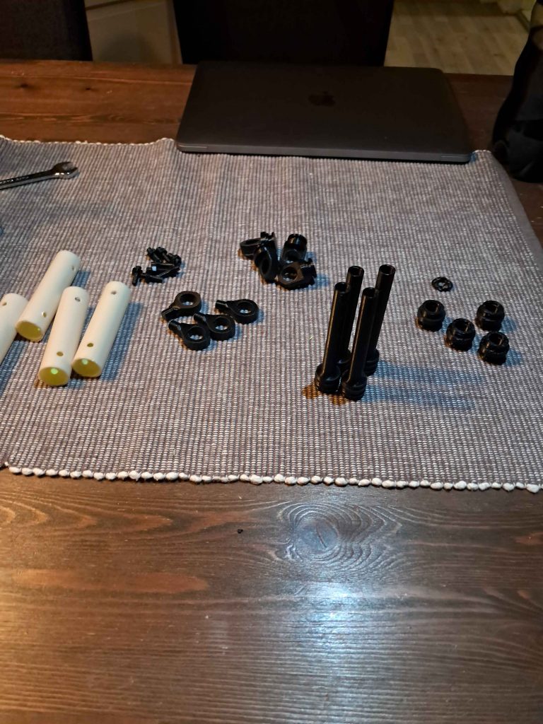
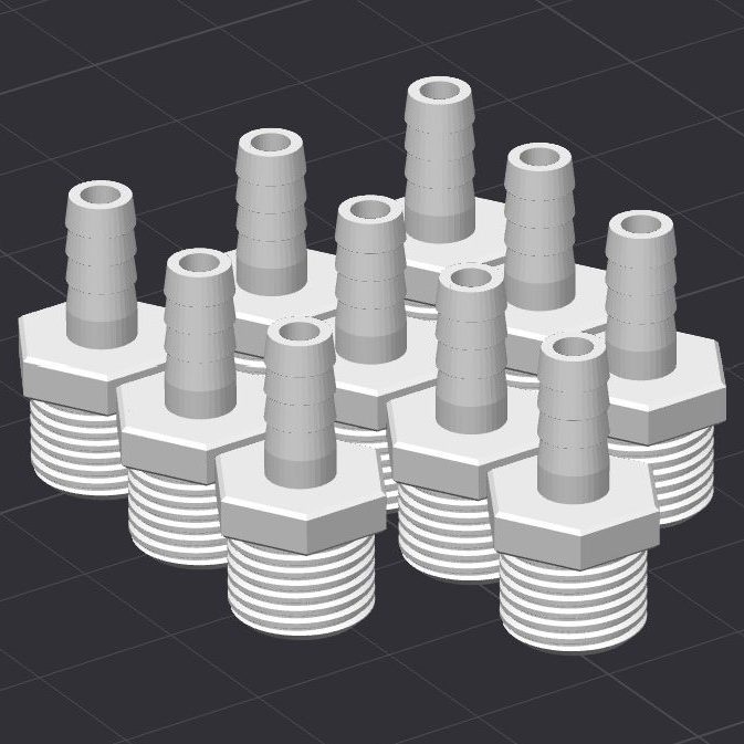
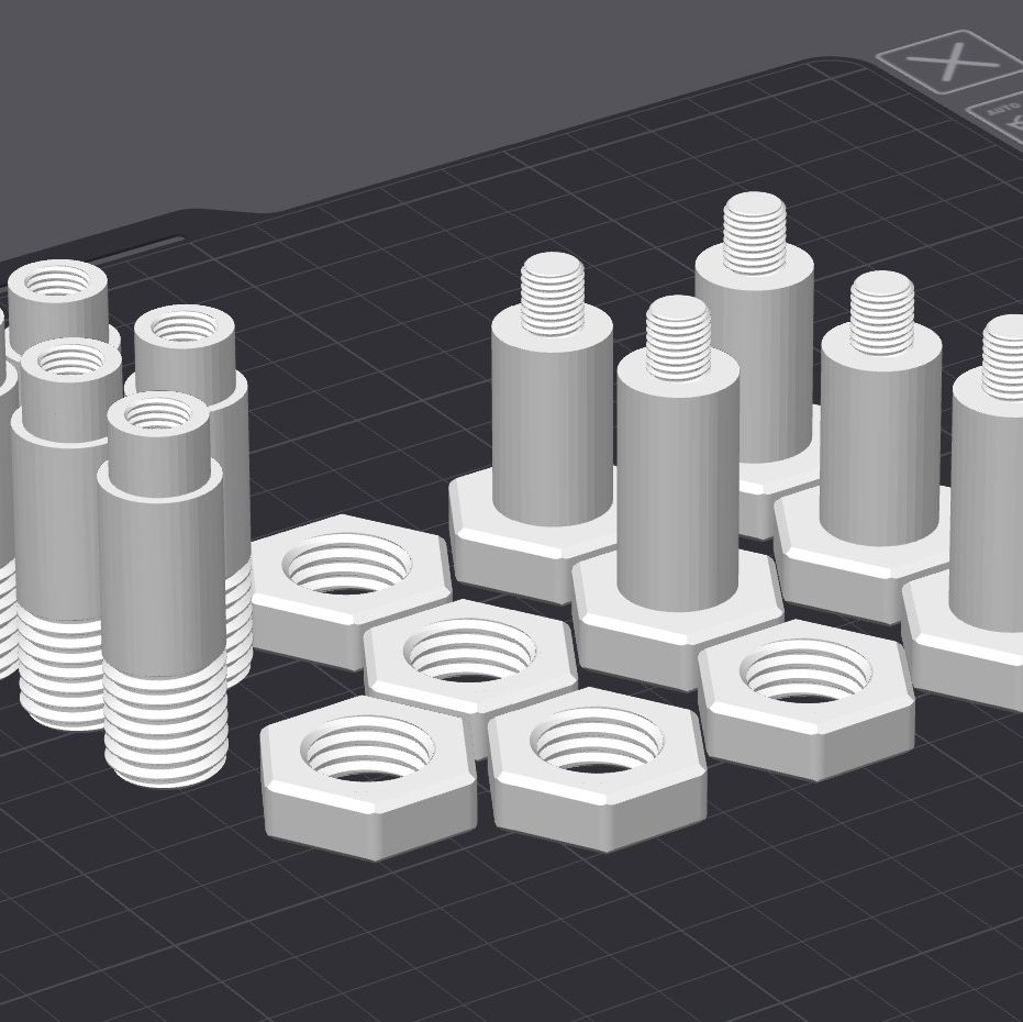
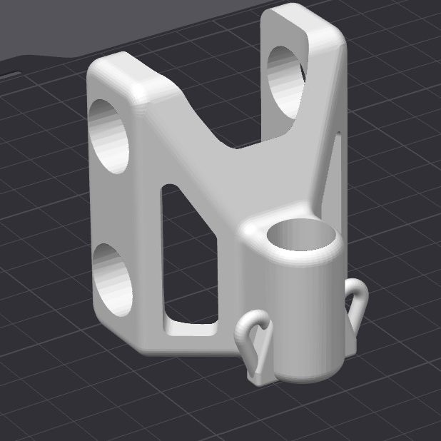
Other critical parts of the system that needed to be printed was the remaining attachment to the valves, and the remaining cylinder attachments. These were components that I have designed previously, so they only needed to be printed. I also printed the marker holder prototype, which will attach the marker to the arm using an elastic band. With these parts printed, and the valves made, I could do an integration test of the valves on the arm. This was to ensure everything could be mounted as intended, which ended up being successful.
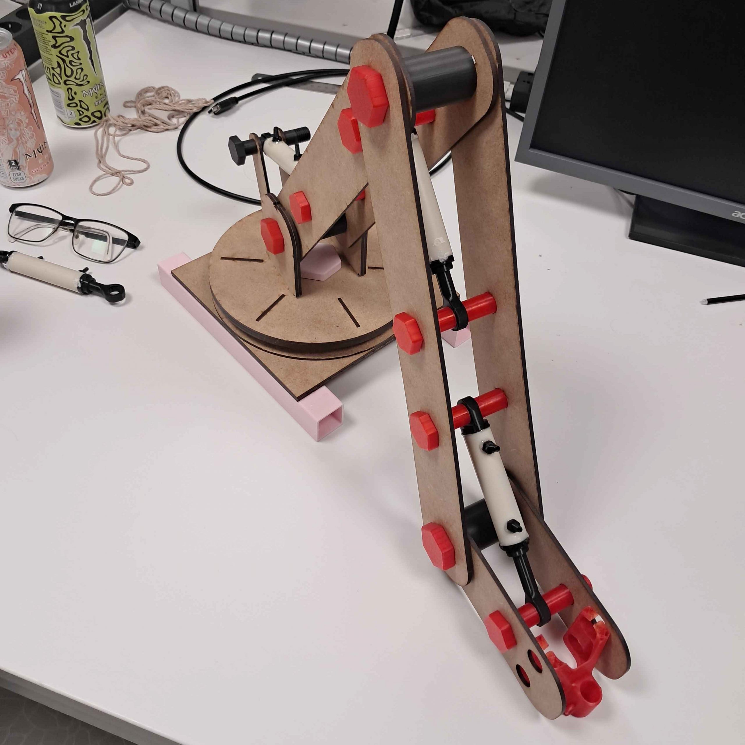
When it was time for the hydraulic system test, all the parts were ready. I prepared the valves by wrapping the valve attachments with thread seal tape, and helped Erling set up the test board. We set up the cylinders, valves, manifolds and pump, and made sure all the hydraulic components were hooked up correctly.
The full hydraulic system test showed me that both the valve attachment and the cylinders worked as intended. Although, the cylinders were not sealed tight enough for comfortable use (water sprayed everywhere). This will be my main focus moving forward.
Lisa:
Following last week’s breakthrough in understanding how the potentiometer, valves, and pump work together, this week has been about putting that knowledge into practice. Together with Syver, we focused on refining the Arduino code, specifically the part where the potentiometer directly controls the valves, and testing it on the integration test.
After spending quite a bit of time last week just connecting the dots and understanding how the system behaves, things finally started to feel more intuitive. This week, the goal was to make the software behave as closely as possible to how the system should act in real life. That involved a good amount of debugging, especially to make sure that each relay triggered correctly and that the valves responded consistently to the potentiometer input. We went through the control logic carefully, verifying that the response timing between the relays and pump stayed stable and predictable.
The testing was done on the hydraulic rig setup. For the first round of testing, we used three potentiometers connected to their respective valves. This gave us a good indication of how the relay system handles multiple channels running simultaneously and provided valuable data for fine-tuning the code.
However, during these initial tests, we quickly noticed that using the potentiometers for manual control was a bit tricky… it was hard to get smooth movements and keep track of how the system responded in real time. To make the testing process a bit easier and more practical for the whole team, I created a temporary workaround: instead of controlling the valves with the potentiometers, I added buttons to manually trigger the extend and retract functions.
This simpler setup made it much easier for us to test the system step by step and observe how the relays and valves behaved without worrying about small fluctuations in the potentiometer input. It was also a great way to visualize the valve logic and confirm that the system behaved as expected.
With the basic control loop now working reliably, the next step will be to expand the setup to include a fourth potentiometer and test all four valves together. This will let us see how well the system scales when every joint is active at once.
We also got to test the software as part of the full system this week, which was a big milestone! Under “Full hydraulic system test”, you can see how the software was used together with the complete setup in action. It’s exciting to finally see everything start to come together.
Syver:
Hello! Last week consisted mainly of math implementation and debugging. This week was pretty similar in that regard, along with some integration work.
Firstly, me and Lisa tested the PID implementation translated from the sim, which needed some debugging in order to work. After fixing the issues, we realized that the .ino file we used had become way too large to easily navigate, so we quickly ported everything to PlatformIO. This made the code base much more readable.
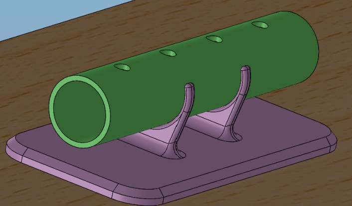
For the arm simulation, I picked up where I left off by implementing the space translation from having the first joint as origin to having the bottom left corner of the drawing area as origin. This allows us to generate normal cartesian coordinates in the drawing space, directly extrapolated from the edge detection algorithms without much pre-processing work for the arm to interpret them. This took some time, but worked in the end. To verify the code, I also implemented a line drawing function in Unity, where a collider against a whiteboard plane triggers a line being drawn. This worked pretty well, other than the line being drawn in 3D space if the end effector origin is too low. This is because I didn’t implement a rigid body collision to avoid clipping. The line being drawn verified the implementation nonetheless.
Here is an attempt at a smiley face! 🙂
It did not draw very well :(. As discussed in previous blog posts, the simulation uses math to try to simulate the pump system based on the binary action rate limitation, making the arm less responsive. There is most likely room for more software optimization, but it is most likely not worth tweaking further before we actually test it on real hardware. Despite the lackluster drawing performance, all the systems operate well!
Much of the remaining work was done with the others in order to integrate and test the system. Since the test was laid out on a testing rig rather than in the arm structure, we didn’t get to test the inverse kinematics. The potmeter PID feedback seemed to work OK, while we still need to improve on our cable management and such. Read more about the integration test in the shared section of the blog.
Emory:
This week, I continued fixing the slider for the website. First, I got some help from Syver in making the slider on the front end for me to use in main to change the value of the polygons that are being shown.
I first tried fixing a slider that would constantly update on the website when you moved the slider up and down. Did get this to work after some trial and error, but did see that this would be too much load on the Raspberry Pi as it read so much of the input from the frontend, it struggled keeping track of all of it. This part also involved fixing some of the front-end, which I wasn’t the most confident in, so I went for the other option I felt better working on.
So then I went back to the start to fix it so it would only update the percentage you have on the slider as you clicked on the load in image.
So, for the code in main, which for this part is the only thing I had to fix, I started by removing the hard-coded part from last week, so that it would not get in the way of testing by making the slider function as I wanted it to. Then it was fixed to contain the contour area and use this in changing the number of contours that will be shown when moving the slider.
I also had to make a new job for main to use in getting the slider value from the front end and changing the sorted contours based on the percentage shown on the slider. It also starts by showing the biggest polygons to make sure you get what you want, as you want the biggest part of the drawing and remove the smaller polygons to make it easier to be drawn.
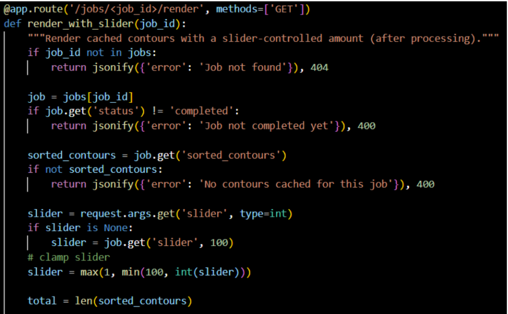
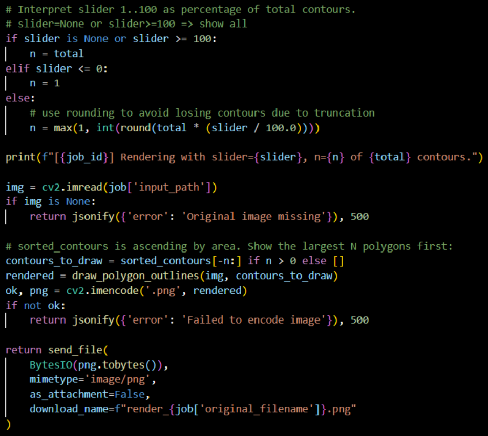
With the new job, it can be run inside the sorted_contours function to work with the rest of the code that processes the image being sent in. The result of the job then gets shown.
Also removed the sleep from the function, as we don’t really need that, as running this on the Raspberry Pi will likely take longer than my computer can run it anyway, so it will be shown in a reasonable amount of time.
Here’s a video showing how it works on the website with the slider now:
Erling:
I have worried a lot about other courses and obligations this week, however i have laid down a serious effort and sacrificed a bit of sleep quality in order to make some real progress this week.
I continued the work from last week by gluing up the manifolds with epoxy glue. i discovered that i made a design error, and that i needed new prints of the endcaps rather quickly, luckily Richard was very helpful and printed the new pieces in just a few hours. Using the printed pieces and the tube from last week, the manifolds were glued together and left to dry overnight
When we returned later to put together a testing setup i had the extremely disappointing experience of snapping one of the printed hose barb fittings, rendering the manifolds useless. This was a setback, and i had to redo the glueup job. This meant cutting new tubes, and reprinting all the printed parts, this time in stronger materials. I then glued the new manifolds and let them sit overnight for the glue to harden.
We planned a full system test to see how the hydraulic parts performed. In order for this to be somewhat organized i made some simple holders for the hydraulic components in CAD and 3d printed so that we could attach the parts to a plate and hook everything up in accordance with the hydraulic schematic shown in a previous week. After printing and getting a plate from Richard, i used hot glue left over from the water rocketry event during Fadderuka to attach the mounts. This worked pretty perfectly, as it made for a satisfactory bond, while still being removable without damage to the plate.
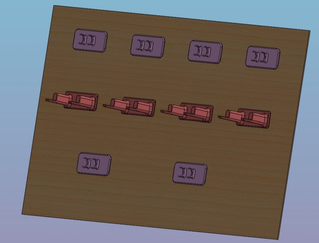
During the system test, i discovered that i had made the holders for the manifolds and cylinders way too weak for the loads applied during assembly of the test stand, and broke several places. I will redesign these, and print new ones to better handle the treatment that we have to expect for our system during function testing.
I also learned during testing that we have leaks in the manifold. This seems to be mostly between the hose from the pump and the 3d printed hosebarb on the distribution manifold. There are also leaks in other places such as the smaller hose barb pieces. This is understandable, as they are only really held on with small zip ties. i believe that these leaks can be mitigated by using a small size hose clamp on each. This is an area with a good potential for improvement.
The next weeks will be spent working toward sealing the leaks, and integrating our hydraulic solution with the electronics and software to create a working system.
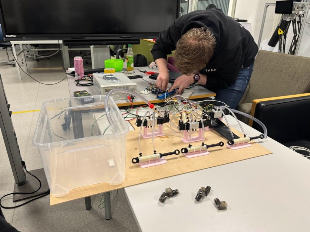
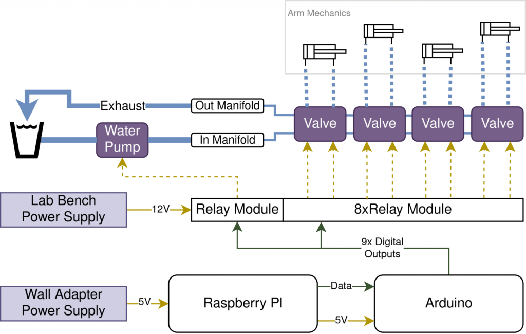
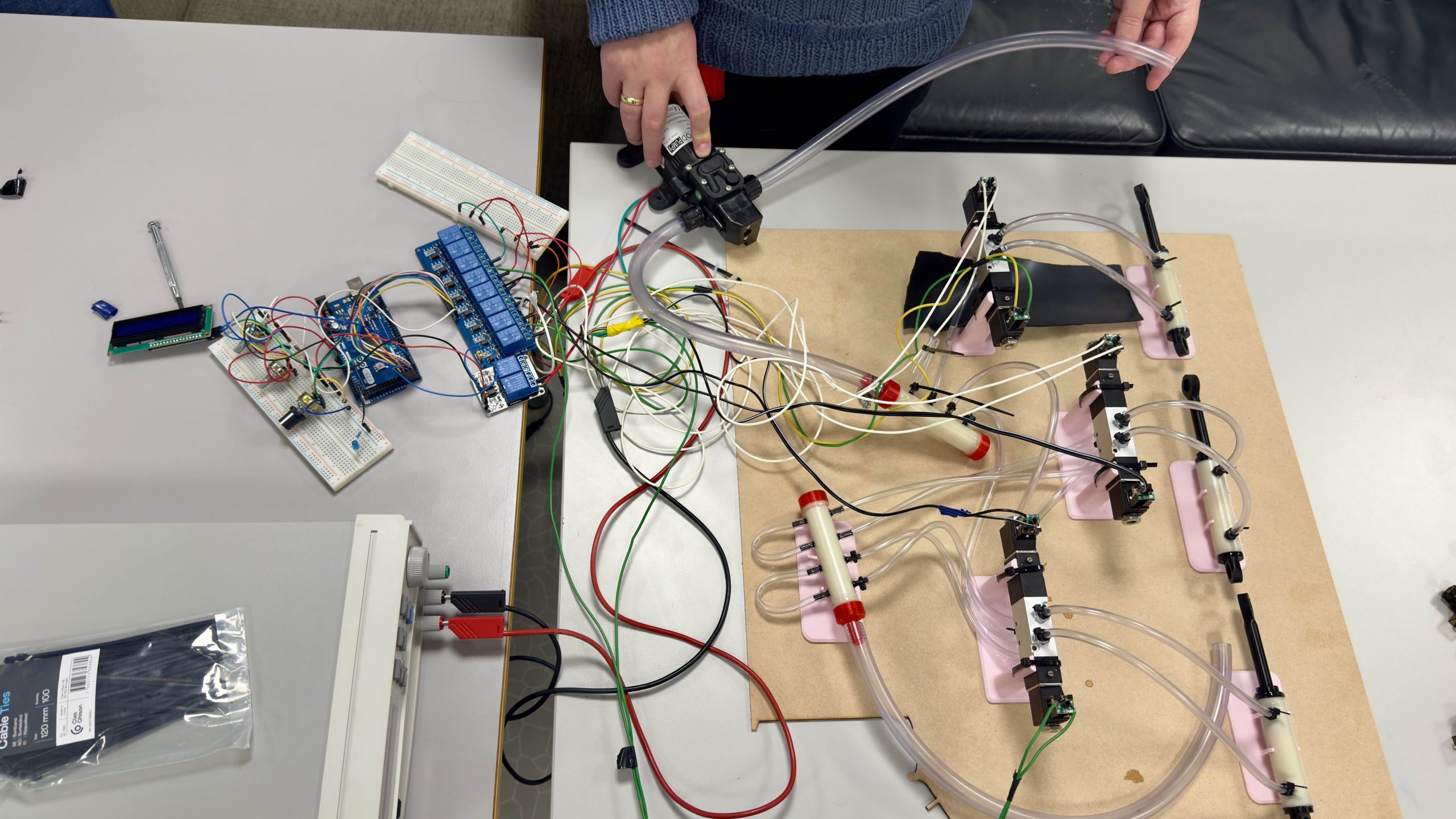
Full hydraulic system test
To test the system, we laid out the hydraulic components on a board and connected our two power systems up. We’ve visualized the system in this graph.
With everything connected up, we realized that we lacked some cable management, both electrical and hydraulic. The test was a success, in that all the systems worked together, and the we were able to achieve movement in the piston from user input. There were however lots of tiny problems culminating into a complex mess. These problems were mostly cable management and lots of leaking from the selfmade hydraulic components. In addition, with the automatic PID control using the potentiometers, it was hard to produce stable piston movement for a successful piston control test.
Therefore we decided to extract the needed component for one of the pistons, which reduced the cable (both water and electronics) count drastically. This ended up yielding successful results, though still with a bit of leakage.
We were nonetheless very happy with the outcome!
That’s all for now, see you next week!