Week 10
Bram van den Nieuwendijk
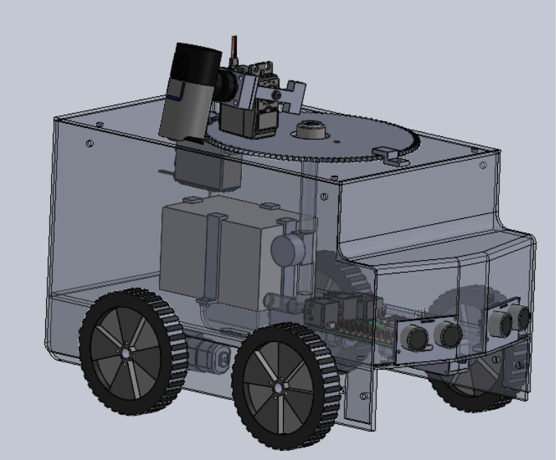
This week, I started by laser cutting the base profiles to begin building the prototype. After the first round of laser cutting, I noticed some interface problems between the parts. I updated the designs and tried again, and this time it worked successfully.
The frame of the car has now been built, so the next focus is on creating and testing the prototype for the rotating top frame. To do this, I’ll need to do some more laser cutting and 3D print a few small parts.
I also spent some time improving the visual design of the car model to make it look more appealing, instead of just a simple square box.
We are still waiting for several parts to arrive, so the base frame hasn’t been tested yet. There’s a chance it might need to be updated later if the actual mounting holes turn out to be different from those in the 3D model.
Rick Embregts
This week all parts have been shipped and the tests to test the boards are designed. See the tests in the images below.
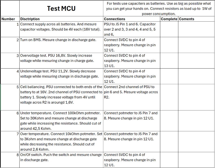

During this week we also found some problems with the electrical design. First priority is to get the entire system tested and operational. Afterword we can look for solutions to the problems.
Sulaf
This week, my focus shifted from standalone obstacle detection and avoidance to integration with the motion control system. Åsmund worked on the motor calibration and implemented speed control functions, which opened the door for me to eventually replace my simulated motor actions with real PWM-based commands.
Integration with Motion Control
Previously, my avoidance maneuvers were simple print statements for testing. Now, I am adapted them to use Åsmund’s speed-setting functions to the best of my abilities, considering I am waiting for the 3D printing to test it out in real time, however I am still This means:
- When an obstacle is detected, my module calls the calibrated speed function to stop the motors smoothly instead of abruptly.
- During avoidance, the robot can back up and turn using real speed values, interpolated from Åsmund’s lookup table for PWM control.
Shared Flag System
The shared flag _is_blocked remains the core of communication between my module and navigation. The navigation system checks this flag before executing any movement.
Code Updates, Improvements & Explanation
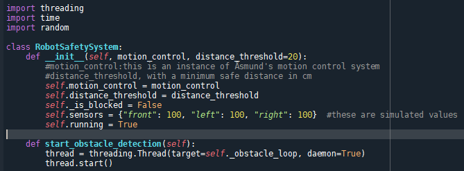
Still using threads for the detection and avoidance while navigating. Decided as usual to print the output to the console for easier debugging, and considering so far that is the only way I can check of the function I am doing are running as they should, seeing I am waiting for the other members responsible for the 3D printing and assembling the robot to be completely done. However, this still does not affect the code for obstacle detection and avoidance I am doing, having simulated results for the sensors. It is quite easy to replace them with actual readings later.
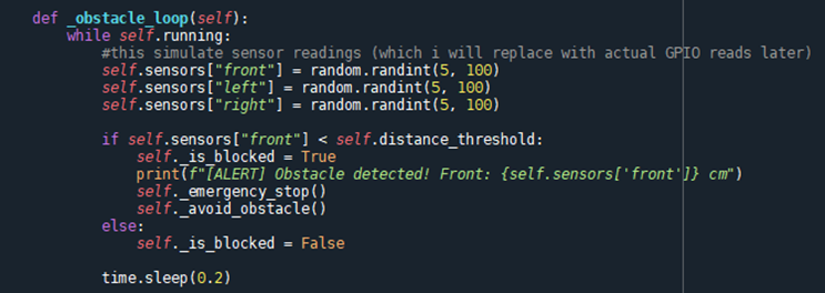

The obstacle detection alerting if there is any obstacle by checking the sensors as always, and emergency stopping if needed.

Here I maneuver around the obstacle when the object is detected, and decides which turn to take depending on the sensors.
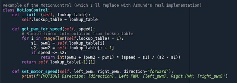
Making my own MotionControl that to simulate Åsmund’s code. The reason being that I need a testable environment to validate my own obstacle detection and avoidance logic. By making a MotionControl Class, I can mimic Åsmund’s interface (the set_motor_speed() and get_pwm_for_speed()), this way I can ensure compatibility early, further easing integration before it happens, rmaking sure that the integration will happen smoothly, and that my module and Åsmund’s will work well together. This way I can also run this independently without depending on Åsmund or having to wait for the complete finished module, I can work on my own time and test my code early. Also, this way I can stimulate realistic behavior, so even though I am taking a small portion of Åsmund’s part, it proves to be useful to my part at the end of the day.
Testing & Results
Simulating the calibration and running the code:

Since the physical robot is still not available, I continued using simulated sensor readings. However, the motor commands now reflect actual PWM values rather than placeholders, making the transition to hardware more seamless for later.

Here you can see the start, from navigating to detecting an obstacle (obstacle detection segment), stopping, then navigating around it (obstacle avoidance segment), then proceeding to navigate after the obstacle has been avoided and maneuvered around. This week has been quite fun, I got to integrate my module with a simulated module of Åsmund’s by my own recreation, keeping it as close to the possible end navigational system for the MotionControl function class, to ensure full integration.
Åsmund Wigen Thygesen
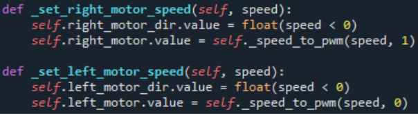
This week my goal was to make a program to “calibrate” the motors and implement the set motor speed functions in the motion control system.
The calibration is pretty simple, I just need to run the motors with varying PWM and sample the speed it is going at each specific PWM value. Then we can graph it and/or copy the values directly and use this to set the correct PWM value when we want to run the vehicle at a specific speed.
This approach should be pretty reliable as long as we have the correct load when running the calibration.
Implementation was pretty straight forward, set a pwm value on each motor, wait a little to make sure it’s up to speed, set the traveled distance to 0, save the current time and wait a predetermined amount of time.
The distance variable will be updated with every encoder step in separate interrupt functions, then after the specified time we just divide the total distance for each motor by the time since we reset the distance.
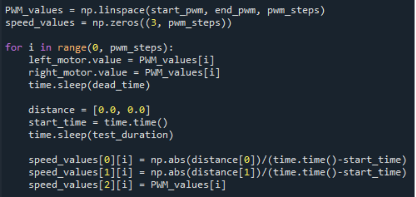
Now we have a lookup table for speeds and the corresponding PWM value.
Now for the implementation in the motion control system, we store the output from the calibration in a variable in the motion control system, then we mostly just need a function to convert a speed value to a PWM value.
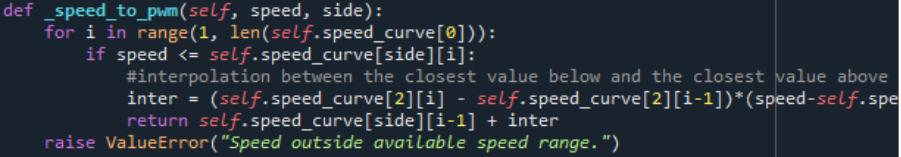
This is done by simply iterating through the lookup table until we find the first value that is greater than our desired speed. Then since the speed is in ascending order we can interpolate between the closest value above and the closest value below the desired speed.
Then it’s just a matter of setting the motor direction and PWM accordingly