Sondre:
This week, my main focus has been on combining the IMU with the ultrasonic sensors to ensure the robot can maintain a steady heading throughout the course. Previously, the robot relied solely on the IMU for heading correction. However, this approach had limitations: the robot lacked awareness of its distance from the walls, and the heading correction alone was not always accurate.
By letting the IMU handle orientation control while the ultrasonic sensors provide real-time feedback on wall distance, the robot can now make smarter course corrections. It not only maintains its heading but also keeps an equal distance from the side walls by strafing slightly left or right. This implementation marks an important step toward making the system more reliable, smoother, and better adapted for precise navigation.
My first implementation expanded the isClear() scene logic. The robot first checked whether it was off course using the IMU, then checked its lateral position using the side sensors. The pseudocode for this approach looked like this:
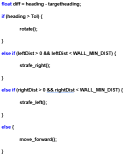
However, this implementation did not work as expected. The behavior was laggy, and the robot often failed to correct its heading when needed. Additionally, I had no control over how fast or how sensitive the corrections should be. To address these issues, I decided to implement a PID controller, which allows for smoother, continuous adjustments and precise control over both speed and sensitivity.
A PID controller is used to continuously correct the robot’s movement based on feedback from its sensors. In our project I feed the data coming from the IMU and ultrasonic sensors to the PID-controller in real-time. The controller then calculates the difference between the desired values and the actual values (error). With this calculation the robot then knows what to correct and how much to correct.
wallError = rightDist – leftDist;
wallErrorSum += wallError * dt;
float wallDError = (wallError – lastWallError) / dt;
wallOutput = wallKp * wallError + wallKi * wallErrorSum + wallKd * wallDError;
Here, the first line finds the difference between the two side distances, showing how far off-center the robot is. The next two lines handle the accumulated and changing parts of the error, making the movement smoother and preventing overcorrection. The final line combines everything into one value, wallOutput, which tells the robot how much to strafe left or right.
float strafe = wallOutput * 0.3f;
Positive values make it move one way, negative the other, and the size of the value decides how much to correct.
This calculation is also implemented with the IMU, giving the robot continuous feedback on its heading and allowing it to both rotate and strafe at the same time. By combining the IMU-based rotation control with the ultrasonic wall-distance control, the robot can correct its orientation and side position simultaneously. This results in smoother motion, less oscillation, and a more stable path through narrow or uneven sections of the course.
I also updated the function that helps the robot check whether it’s on the correct heading after completing a 90 degree turn. Previously, it only checked the heading once after the turn was finished, but now it makes small corrections if the heading is off. You can see this behavior in the video at the bottom of my section. After turning, the robot pauses for a few seconds (a bit too long right now) to let all sensors update so it doesn’t use outdated data. It then corrects its orientation to be exactly 90 degree or 180 degree relative to the starting direction. This process isn’t perfect yet, but it consistently checks and adjusts until it’s within a 1.5-degree margin of the desired heading.
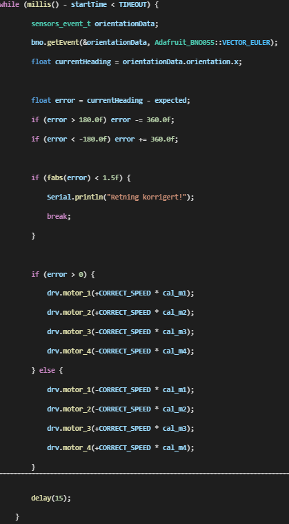
Here is the part I added to make it rotate if it is of heading after a turn. I have added that if the heading is within 1,5 degrees it is good.
With all this done, the robot is now noticeably more precise and stable in its movements. However, there’s still room for improvement. The next step will be to fine tune the PID parameters to find the perfect balance between responsiveness and smoothness, making sure the robot reacts quickly to errors without overshooting or crashing. I also plan to polish out a few remaining bugs, especially related to timing and sensor updates after turns, to make the motion more consistent.
https://youtube.com/shorts/dDDXDmNOyAo?feature=share
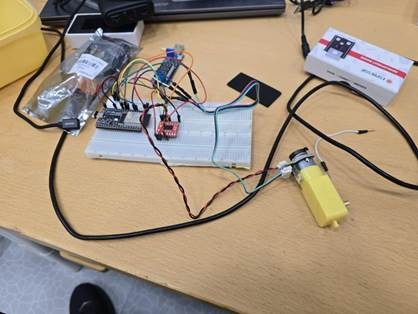
I also experimented with using the ESP32 microcontroller to see if it could control a motor and read encoder signals. I connected both the motors and encoders to the ESP32 through a standalone motor driver and used a simple test code from ChatGPT to try it out. However, I ran into some issues at first, my PC couldn’t communicate with the ESP32 because the required drivers were missing. After installing them, I tried again, but still had no success in getting the setup to work properly.
Since this isn’t the solution we plan to use right now, I decided not to spend too much time troubleshooting it further. Still, I’ll need to get the ESP32 working with the encoders later on, as the micro:bit doesn’t have the processing capacity to handle encoder signals directly. The ESP32 will therefore act as a middleman, reading the encoder data and sending it to the main controller when we implement the new motors.
Anette:
After talking to Steven about how to proceed I am now going to attempt to make a microcontroller using the NRF52833-QIAA-R. I have therefore been researching the process and comparing the Micro:bit in order to see what I need. This is a complicated process and I have limited time, but due to the exam being the 19.12 i hopefully have time to finish it and order in the next few weeks.Furthermore we also got the new motors and we are getting the batteries at a later date.
Theo:
This week, I mainly documented myself on the A* algorithm, as discussed, in order to understand how it works and how to use it in our project.
Here is the playlist of the videos I watched:
–https://www.youtube.com/watch?v=-L-WgKMFuhE&list=PLFt_AvWsXl0cq5Umv3pMC9SPnKjfp9eGW
–https://www.youtube.com/watch?v=ySN5Wnu88nE&t=1s
I also received a code from ChatGPT, which I adapted for our car. But I couldn’t test it yet.
Robin:
I am watching this video to better understand how it works and why it is necessary:
Balancing unit (BMS) for Li-ion batteries
3S 6A BMS
Balancing unit (BMS) for Li-ion batteries The problem I encountered with the videos found on the internet is that many talk about how to charge a BMS safely, but few [talk about] how to make it a discharge protection, which could just as easily damage the batteries. So I continued my research and I found this site:
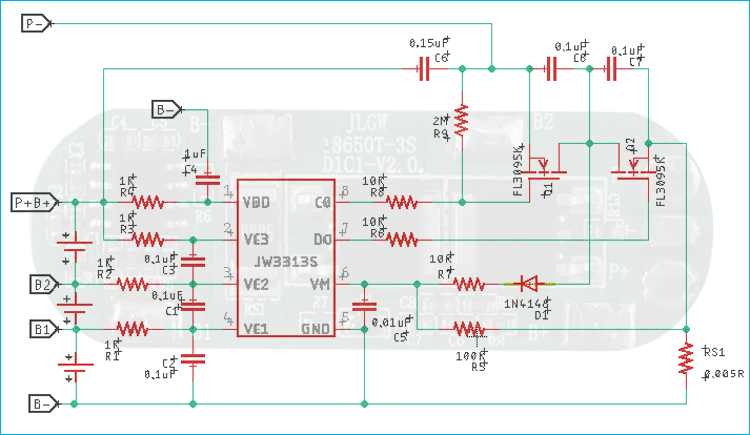
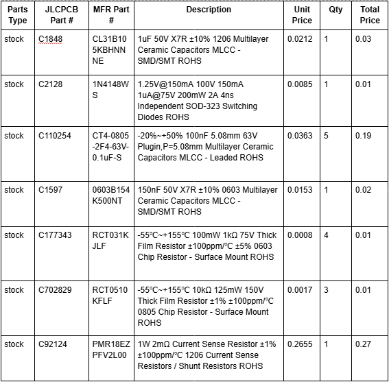
From all this, I can draw up a list of components and move on to the electrical design.
Matias:
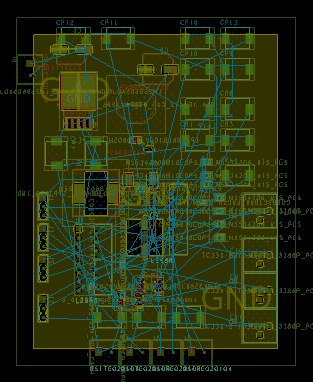
This week, I talked with Steven about adding active filters to the circuit. The goal is to adjust the PWM step and achieve smoother motor movement. It’s a great improvement for the system’s performance, but it also introduced some new design challenges.
After adding the active filters, I realized that the available space on the PCB became much tighter. I’ve been having some difficulties with the routing, especially trying to keep proper spacing and clean signal paths. Because of this, I spoke with the team to see if it would be possible to increase the PCB size a bit. Having more space would make the layout process much easier and allow for a cleaner, more reliable design.
Overall, this week has been focused on balancing performance improvements with practical design limitations. Hopefully, I’ll be able to finalize the PCB layout soon once we decide on the board dimensions