Wang
This week I have continued working on the joystick for micro:bit. I still haven’t received the controller/joystick we will use, hopefully it will come next week. What I have done this week is mostly tried to continue working on the joystick code in zephyr. I had some problems that I haven’t quite figured out, but I think it’s in CmakeListen that it pointed to the wrong path, but it has now been fixed. Since Oske uses zephyr version 2.5.1, I tried to download it to get Bluetooth to work there because now I am on version 3.1.1. Since I don’t have the controller yet, I have tried to control a diode via the joystick. Since it is about the same as what the controller is supposed to do, only it will control a car. I haven’t managed to do it yet because I have struggled a bit with getting errors around this code.
static const struct gipio_dt_spec = GPIO_DT_SPEC_GET(DT_NODELABEL(test_led), gpios);It was suspected that the error may come from something in the designtree being changed because of the example code that I use for bluetooth but I’m not sure.
So now I’m making a new code without bluetooth where my goal is to get a led diode to blink based on how much on the x or y axis I move the joystick. I’m building it now on 2.5.1 and using Oskaras’ code as a start for the joystick.
https://github.com/OskeLTU/Zephyr_code
Oskaras
This week i had the mission of setting up the pwm controls for the car. I started working on the setup i hade before but only actually using the pwm signals. In the overlay file i hade them setup as Inverted, meaning when they were low than the power was HIGH. I went on working for a long time on a flawed attempt since only later i found out that you can’t mix methods of use.
Explanation: When i started working on the pwm i set it up using dt spec. the same way that i set up the gpio pins. the only problem is that if you chose to “bind” the nodes in that manner you are then locking yourself to specific functions for pwm control something that i wasn’t aware of at the time.
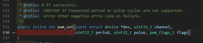
this is the function i tried to use, since i saw some examples of using this.
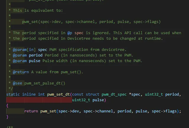
and this is what i needed to use. as you can se they are fundamentally the same since the pwm_set_dt even uses pwm_set function. but i tried to use it without converting the specs to readable variables for the function hence it did not work. Now my pwm pins are set completely different and using binding instead of dt_spec. and now i use pwm_set and it works. The pwm.c file has helper functions for the pwm so that i don’t have to write out the whole thing each time i want to use it. in the future i want to streamline this even more where i can specify what device i want in the function as well since now i have 4 different ones for the pins.
pwm testing with the led:https://youtu.be/JHrK39vtiVQ
the explanation for the test is in the video so please watch it.
and the applied pwm to the car is here: https://youtu.be/MBZ3YuX8j8I
Here is the last commit that merged into the main tree from the pwm testing there you will see everything that was changed: https://github.com/OskeLTU/Zephyr_code/commit/f467490e13eb1676462097c2d4cfea3f8ed0b3f1
Another thing that was very difficult was the pin setup. since only later on i found out that the pwm peripheral has 4 channels to them so i could have used only one. and in addition to that i found out that not all pins support pwm functions. so that is why i routed the pwm pins to the first four and changed the gpio pins accordingly.
discussing some functions:
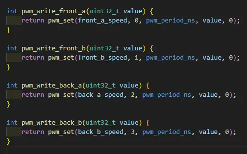
This could be made a lot simpler by just passing the device pointer as a variable and sending it further to the pwm_set function, but it’s the same block of code. The only downside with mine now is that if i want another pwm signal i have to write out another function
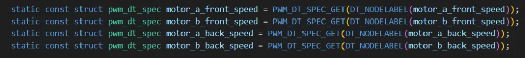
the binding:
this is the old method:
and this is the new method:
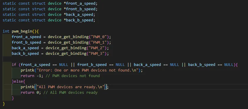
so the biggest difference is that when i call the function pwm_begin i initialize the pwm connections. in the old method they are initialized at runtime. i will keep the new method since it works.
Øivind

When I need a break from digesting heavy theory, it’s nice to sit down and relax, weigh things in my hand, screwing and unscrewing just to get the physical aspect of what I do. So, by creating something that is by far a good choice, often in error I can find the solution. I appreciate this project by the combination of a physical object that I can see come alive through logic from the electronic and mechanical parts merge.
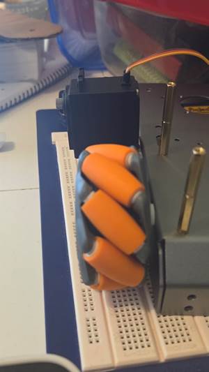
The servos steer clear of the wheels!
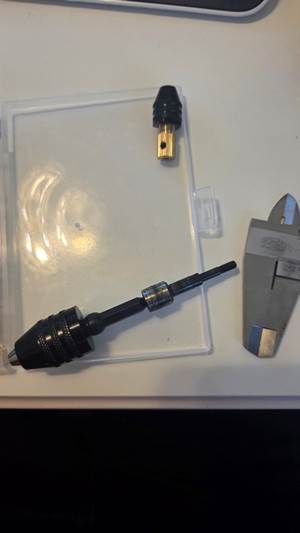
Drill-bits for the drill-rig. One part is MIA and adds to the stress.
Today I whipped out the fine China! Brand new soldering iron, which before I do anything else I have to prepare and test before I dive into soldering on components I need. I started desoldering a couple of capacitors and will go on to the BMS when I feel safe with the new iron.
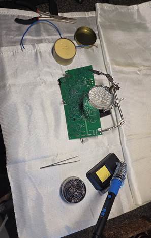
The test solder went better than expected. Beginners luck, maybe? YouTube, absolutely!
It was beginner’s luck. 1,5 days went into a lot of work, but almost no progress apart from learning, and on Friday I’m back where I started Tuesday. Well, almost back to the very beginning to be honest, but got help from Wang, a fellow member of our group. He had soldered some of the exact parts I’m using and gave good advice. Thank you!
Off to school to meet up with the group!
I finally visited Richard and tried to explain my plans. I left with my dreams broken, advice and new ideas. At least I still have a clear path but will scrap many ideas I personally think is good because the main priority is to make this happen (the Rover that is). Richard showed me ways to handle obstacles regarding building the car I did not see at an earlier stage and hence, had not considered. I guess Richard has solved a problem or two before. Servos are now picked off the Rover, and I do not know where to start again.
I’m not sure if I’ll make it to Christmas since all the setbacks and new iterations are taking a toll on my mental and physical health. Anyways, Happy Halloween!
Stubborn wires and connectors:
No one got hurt in the filming, except my self-esteem.
Monday morning, I need to tidy up my workspace and grow some discipline to focus on one thing at a time. Nothing is going as planned and it is frustrating.
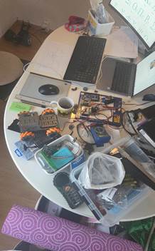
So, after cleaning the clutter, I need to finish off all half-finished parts and start with the drawings of new ideas Richard embedded in my head.
Zardasht
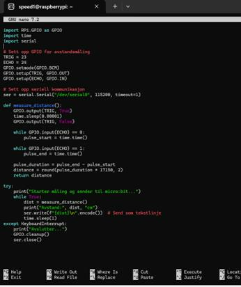
This week, I focused on establishing serial communication between a Raspberry Pi 4 and an Arduino board. The goal was to send sensor data—specifically distance measurements—from the Pi to the Arduino as a test for our upcoming project.
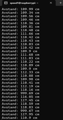
I used an ultrasonic sensor connected to the Pi and wrote a Python script to measure distance and transmit the values via the UART interface. On the Arduino side, I created a simple sketch to receive and print the incoming data.
After some debugging with baud rates and wiring, the communication worked reliably. This test helps ensure that our system can handle real-time data transfer between devices.
If everything continues to work as expected, I plan to expand this setup to the microcontroller we’ll use in the final version of our project.
Henning
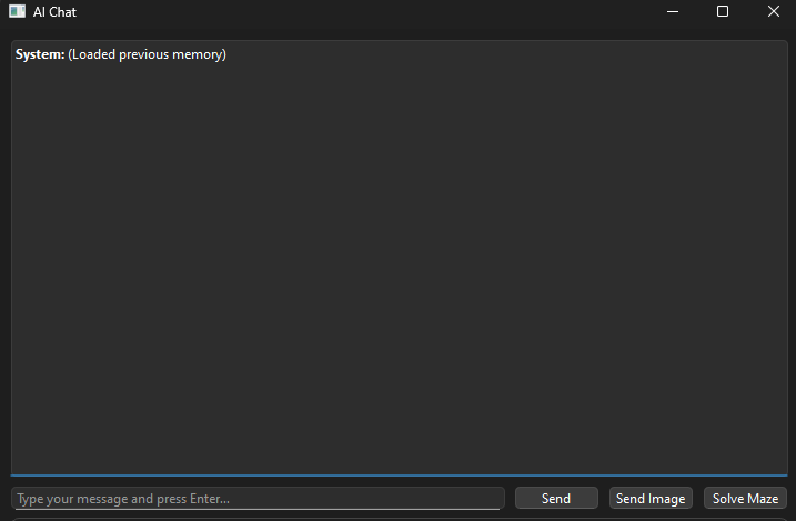
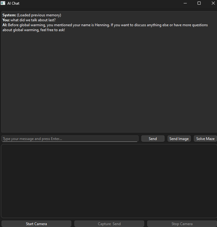
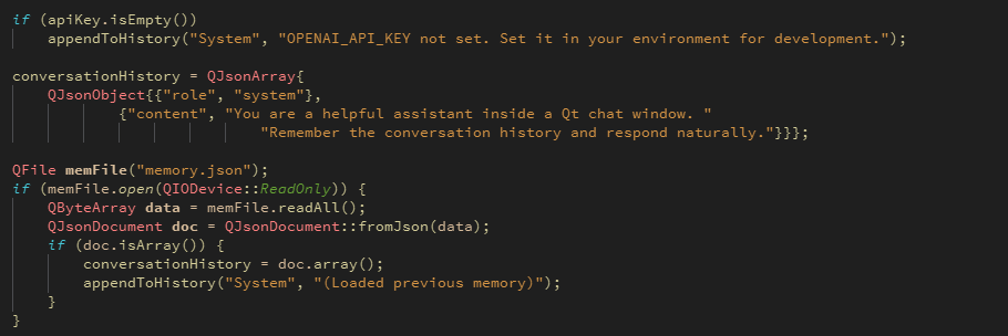
So as i mentioned, last week i stopped with the focus on the drawing of mazes as it became a struggle. I changed my focus towards the memory for the AI and i succeeded. The picture bellow shows that every time i open the AI chat window it shows a message saying “Loaded previous memory”. This means that all the chats and messages between me and the AI is being stored in an empty array which will continue to expand, but simply it holds all information shared between us.
The next picture illustrates just how well it works. Even tho its somewhat out of context, but i told the AI my name, and simply asked it if global warming is real. Yeah… odd question, but it was all to simply test if it worked.
So on that note, really happy with my progress so far. Now all i have left is to make the Ai draw the mazes correctly, and make some easy code so i can connect easily to a Raspberry Pi, or any other sort of connection point. I want the AI to be easily accessible from other sources too as it can provide more solid in case there would be a problem with the Rasp Pi.
For code reference to the memory of the AI:


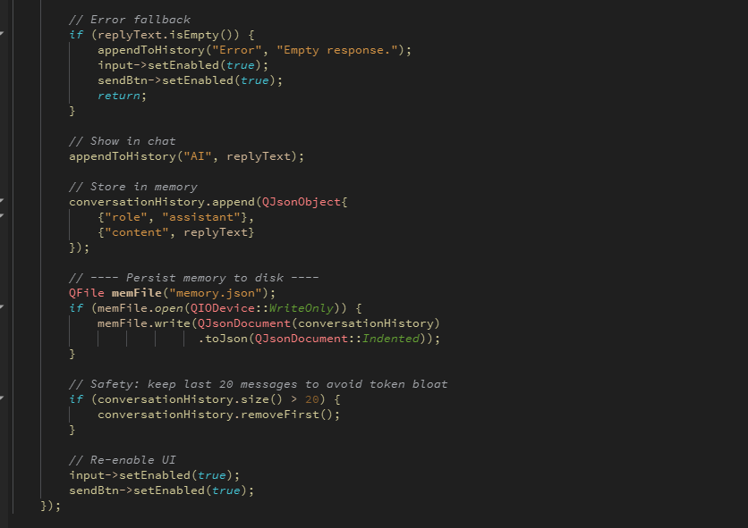
Changed the postChat function. Had to simply rearrange the code and add a few lines. A good note to this is specifically the “conversationHistory.size”. As per now, i have set a limit to the storage to 20 messages stored.
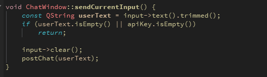
Lastly i did a small tweak on my “sendCurrentInput” function. I removed the append function which originally was in here. But as the “postChat” function shown above now does that job for us. Its not needed in this function.