Hello and welcome back!👋
This week wrapped up sprint 4. Some things didn’t go entirely as planned, but we still made progress across both hardware and software. Here’s a quick look at what everyone’s been working on👇
Fredrik:
Since this week is the end of sprint 4, we were supposed to have a full hydraulic test. Unfortunately, this is not the case. I have been fully preoccupied with another course this week, which has led to very little focus on the hydrawlics project from my end.
However, most of my work this week was things that could run in the background, that for the most part being 3d-printing components. I have been helping out the other members here and there, but my task was mainly to make the four cylinders, and the remaining cylinder attachment rods that I designed last week. This meant that I could do some of the busy work for this project, while also working on the other course. The printed parts are mainly the ones that I designed in week 6, that being the hydraulic cylinder components, with the design changes I made last week.
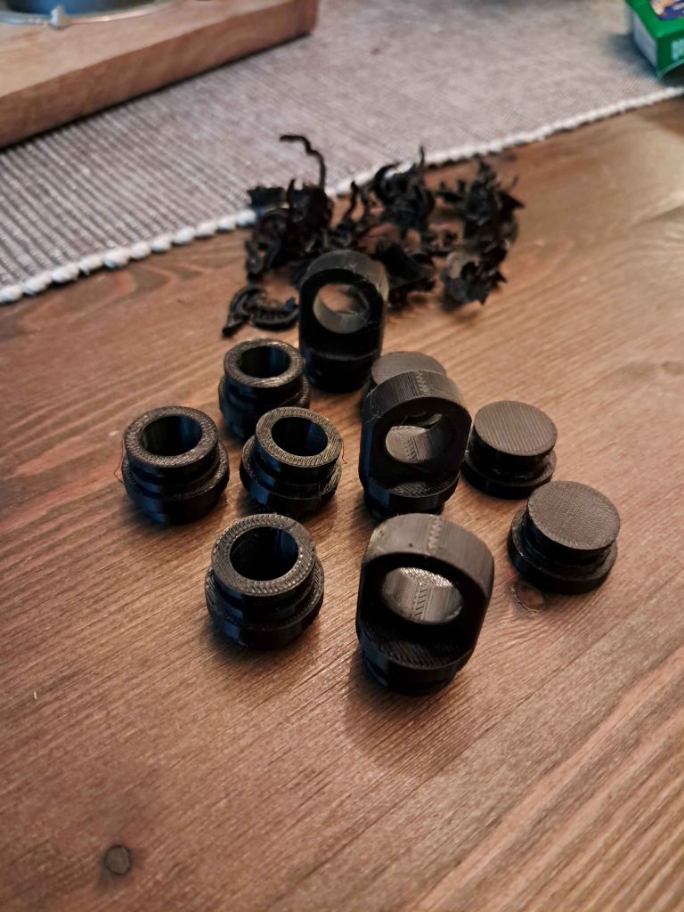
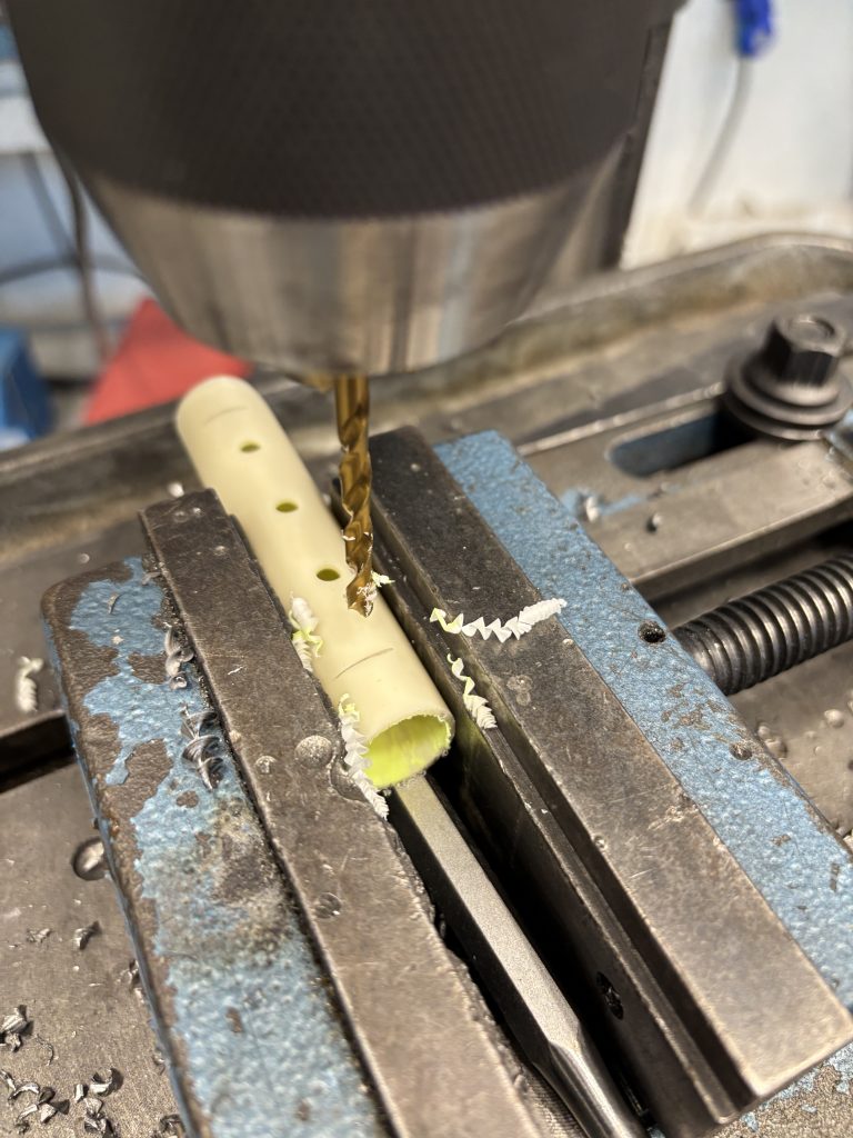
A while back I bought a long tube of diameter 20mm pvc pipe at Clas Ohlson, and used this as the base of the hydraulic cylinder. Now that I know the exact dimensions and features of the cylinder, I can finally put it to good use. Me and Erling used the prototype lab at school to cut the pipe into 80mm segments with the bandsaw, and drilled 4.5mm holes on the tube surface with the column drill. Erling also designed his manifolds to use the same tube, so we made his segments as well while we were at the lab.
As of the writing of this blogpost, I have not put the cylinders together. But the components are printed, the tube is made ready, and the epoxy glue is bought. The only part missing is buying some more o-rings. This means that early next week, the cylinders should be in place. So keep an eye out for the next weeks blogpost, as we might have been able to do a full hydraulic test of our system
Lisa:
After last week’s test, where the valves and pump finally worked together as intended, I had one of those moments where everything looked great, but something still didn’t fully click in my head. The system behaved exactly like it should, but I realized that I didn’t quite understand why.
So, this week was less about running new tests and more about connecting the dots. I wanted to understand better what actually happens inside the system, from the moment a new target angle is received, to the point where the arm moves, the valves switch, and the pumps’ state changes.
Initially, it was a bit confusing. I kept mixing up which relay did what, and the logic didn’t seem to add up the way I thought it did. But after some helpful whiteboard sessions, and with some help from the team (and a few “ohhh, that’s how it works!” moments), things finally started to make sense again.
Here’s the big realization:
Each valve isn’t just one channel, it actually uses two! One for Extend (E), and one for Retract (R). And the pump? It’s its own little controller that only turns on when the system is in motion. No movement, no pump. Then there’s the potentiometer, which gives us the live position of the joint, in our case, that’s what we call the currentAngle(). The code compares that to the targetAngle(), which is where we want the arm to be.
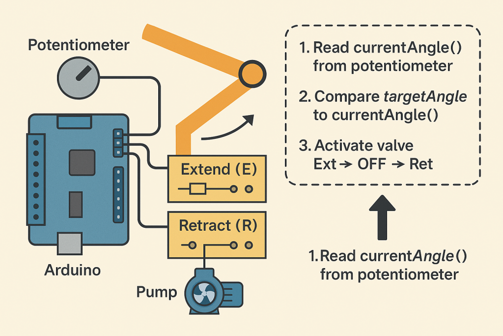
If the two angles don’t match, the system automatically decides what to do:
- If targetAngle() is greater than currentAngle(), it activates the extend valve to move the arm outward.
- If it’s smaller, the retract valve kicks in and pulls the arm back.
Once the two values are close enough, everything stops. That means that the valves go quiet, and the pump powers down.
The coolest part? This all happens automatically. If you type in a new targetAngle() for example, in the serial monitor, the system instantly figures out which way to move and does it — no manual toggling needed.
And honestly, I think that’s what made this week so valuable. I already had a general idea of how everything was connected between hardware and software, through the potentiometer, valved and pump, but this week it finally made sense.
Next week, my main focus will be on refining the setup code and making sure everything runs as expected.I know the wiring and connections are correct, so for now it’s just about making the software align perfectly with the hardware. Once that’s in place, we’ll be ready for a new round of testing to see the full system in action again!
Syver:
Hello hello! This week was a bit all over the place, both in terms of tasks and available time for work. Continuing from last week’s efforts, I finished the inverse kinematic logic. However, implementing the last bit of code for the end effector proved more complex than I expected.
What remained was to fix the end effector segment of the arm, and make sure that its target angle always kept the segment horizontal. This was straightforward to implement, as we had some of the angles available already as bi-products of the inverse kinematics formulas. Specifically, the expression turned out to be;
joints[2].targetAngle = 180 - phi_1 - phi_2 - phi_3; // satisfyingly enoughFurthermore, I needed to implement the math for the coordinate system offset. Last week’s blog post showed how the maths works, but the actual implementation required careful attention to detail (tunga rett i munnen). There isn’t really much to say about this process, other than it being tedious, iterative and time-consuming. After finally completing the logic, the arm moved how I wanted, with the tip of the end effector placed at the given coordinates:
The pull request for adding this functionality documents much of this week’s work: https://github.com/7RST1/hydrawlics-sim-unity/pull/2
I also spent time coordinating with the other members in planning out the implementation, and mapping out the system as it has grown. This included some commenting work on much of the code. I also began designing the logic needed to handle G-code.
This concludes my post this week. There was a lot of problem solving this week. With limited availability and some tricky implementation details, progress was slower than planned. However, I’ve already planned out the next week, and am eager to move forward!
Emory:
This week, the plan was to put in a slider on the frontend so the user could decide the amount of detail they want on their image. So I began by researching how to offer a slider that gives the option to adjust the level of detail in your drawing, and after looking a bit, I decided to go for fixing a slider that adjusts the number of polygons that have been created through processing.
So far, I started by doing a fix value to remove just to check that it would work how I wanted it to. With some help from Syver explaining how the frontend part worked and how the backend sends its data there, I could start by making this work.
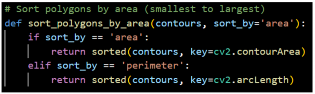
The function above is what I started with to have something to go off of when trying to figure out how to use it in the rest of the code. This is to remove the polygons that have the least amount of coordinates (area of the polygons), so this sorts them from the smallest to the largest.
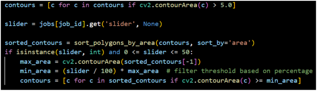
The other part of the code uses the sorting and decide what contours get removed from the image. So far, it’s the specified value coming from the frontend; for this test, I set it at 50.

After quite a bit of figuring out why the code did not want to work, I first realised that since I originally put the sort function to get the coordinates from the CSV file, it got loaded twice, which made it not want to finish loading. So by changing it to use the contours that are already being used for the image being loaded, it fixed the loading issue.
The part that was removing the set value worked in the beginning when I had set the sort function wrong, as it removed the bigger polygons, but when switching, it didn’t remove anything at all. So had to do some troubleshooting to see why. By printing out what polygons and their values were, I saw it gave me 10 empty, which was just noise from the contours, which is a common thing. So by defining contours right before it uses them inside the backend, this fixed the problem of the polygons not being removed.

So after fixing this, the frontend shows the image above. This is a good starting point in fixing a slider that someone on the frontend can use to decide the amount they want to be drawn from their image.
Next, I’ll connect the slider value dynamically so users can adjust details in real time.
Erling:
This week has mostly been dedicated to working on other courses and commitments in my life, so the progress on the project has been a bit lacking.
As promised in the last blogpost, I have started manufacturing the manifolds for the hydraulic system for the arm this week. The CAD models can be seen in the previous blogpost to this.
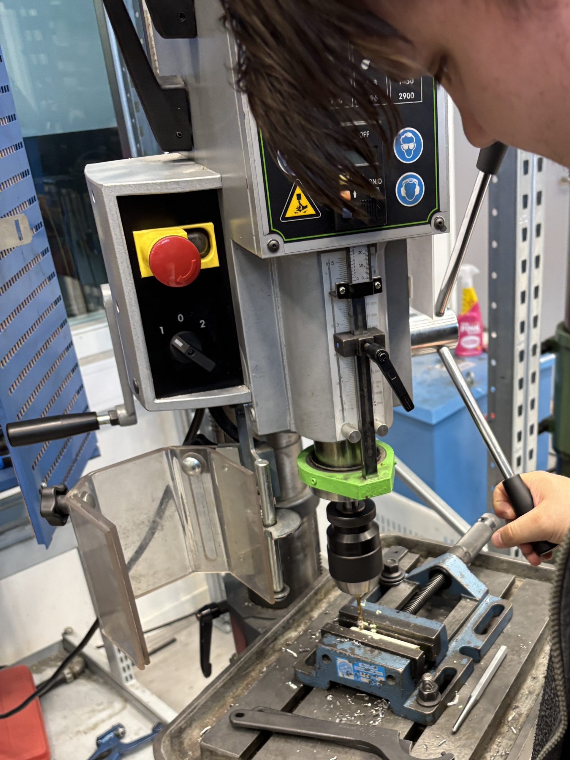
The manifolds consist of a pvc tube with glued on 3d-printed fittings. The tube is cut to length on the bandsaw in the prototyping laboratory. For all these operations i am careful to always have another person in the workshop in the case of injury.
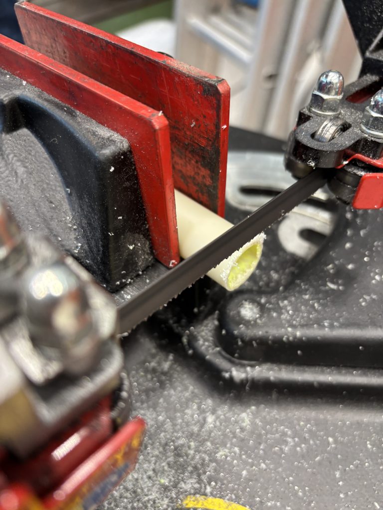
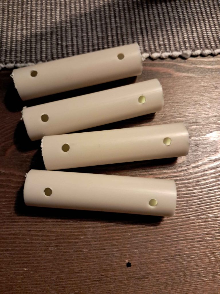
When the piece is cut to the proper length on the bandsaw, i drill the holes for the barb coupling the 4mm pvc tubes on the drill in the column drill with a 4.5mm drillbit to suit the 3d printed inserts. The tube destined for the distribution manifold gets 4 holes, and the collector manifond gets 8 holes.
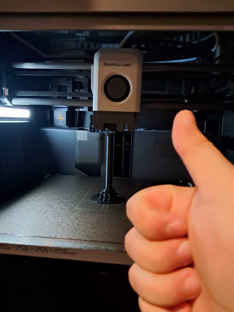
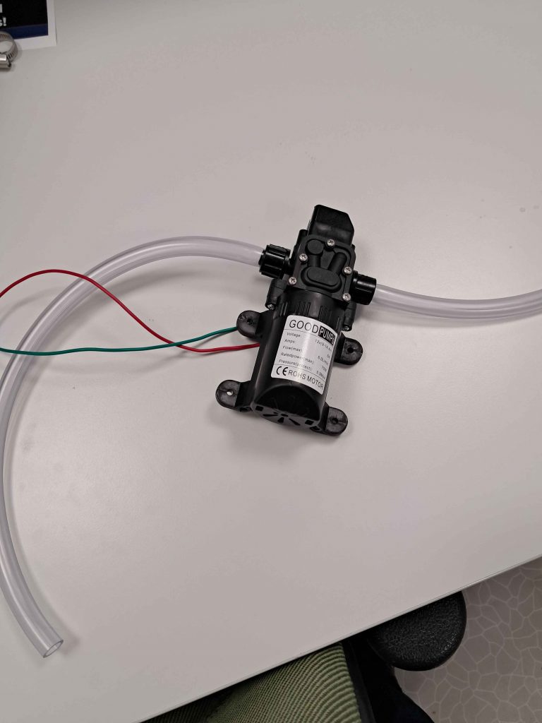
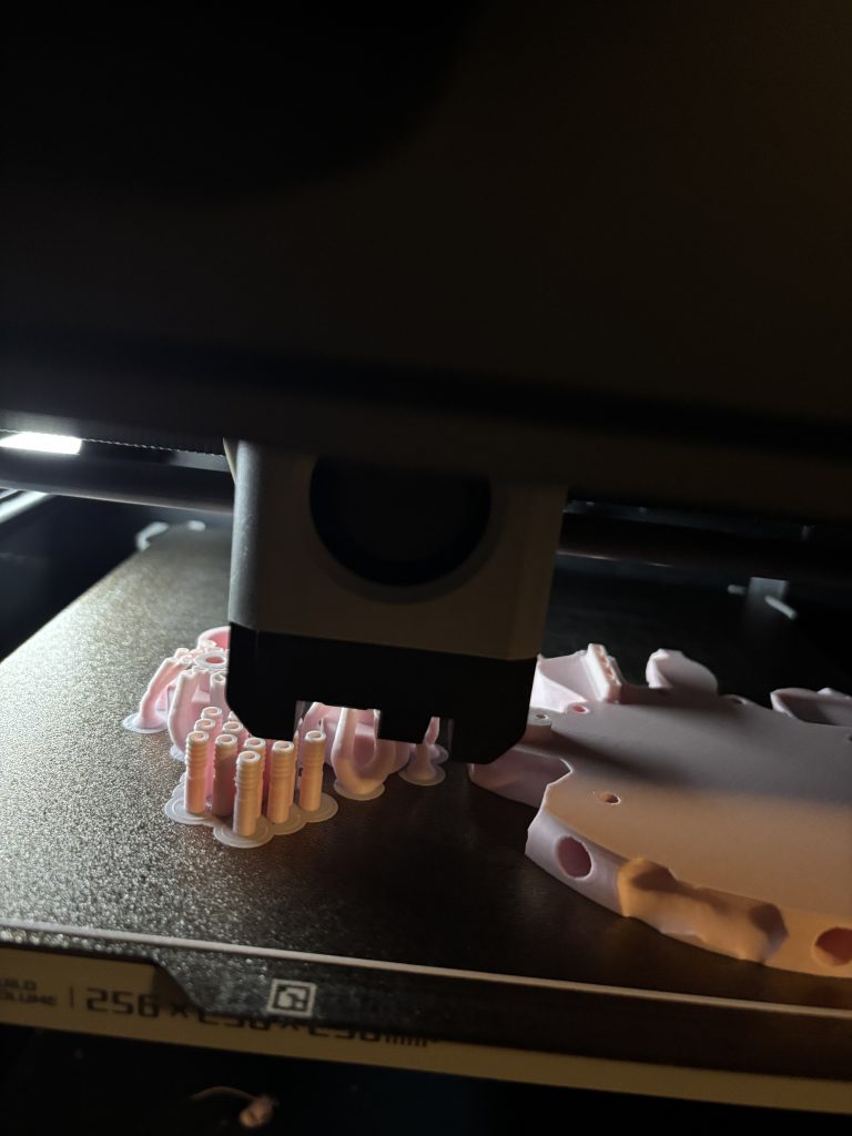
At the time of writing this, my 3d printer is running at full speeeeeeeed. layer by layer building up the rest of the components for the manifolds. When everything is ready i will glue it all together and then we are ready for a system test! We need the manifolds completed rather quickly because we switched the water pump to the 10mm pvc tubing that we bought last week, and now we have to go through the manifold in order to conduct tests. the images below show the water pump with the new 10mm hose and printing the rest of the components.
That’s all for now, see you next week!