Wang
This week I haven’t done much physically since I don’t have the joysick yet but I’ve heard that I’ll eventually get it next week. So for now it’s mostly theory about how I can do it while I learn more to navigate in zepyhre.
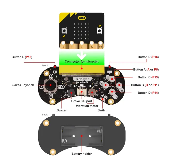
Since I’m not entirely sure yet which joysick I’m going to get, I’m starting with another group that also uses it. They use a “BitPlayer – Micro:bit Game Controller” so for now I’m reading up on it.
So now we have the bluetooth connection that we got from the example code pong on zephyre. The plan is to use that code as a template. It uses buttons to move the plate that the pong ball will bounce off of and if it hits outside of there you tap. The plan is to replace the button input to the joystick. The buttons then use specific gpio they will be replaced with ADC readings. Since a joystick is very much like a potentiometer. You have a potentiometer for the x-axis and one for the y-axis. A joystick works in such a way that when we read the pen from the joystick we have to use ADC i.e. analog to digital converter to get a numerical value that we can accurately indicate how far you move or where it should drive forward or backward.
sources I look at:
Zephyr 101 – ADC + Thread Control
zephyr/samples/drivers/adc/adc_dt/src/main.c at main · zephyrproject-rtos/zephyr
SAADC — Successive approximation analog-to-digital converter
Henning
This week I have met another wall. Could be overall lack of understanding around the libraries that QT provides. For the whole week I was struggling with the draw tool that is provided, and which I showed last week. So, I tried to make the “Solve Maze” button to draw me more accurate maps of certain labyrinths, but it continued to fail. I tweaked on the code a bunch of times but did not hit the mark. I forgot to take a screenshot of all the attempts and changes I did, but I can provide the result for the latest update in the code.
As we can see here, it is clearly not functioning as I want it to. For the next week I will put this part on pause and focus on memory for the AI. With the memory, I want to save previous chats with the bot. After i will look towards possible ways too connect my code / the AI to a microbit or Raspb PI.
Oskaras
next week:
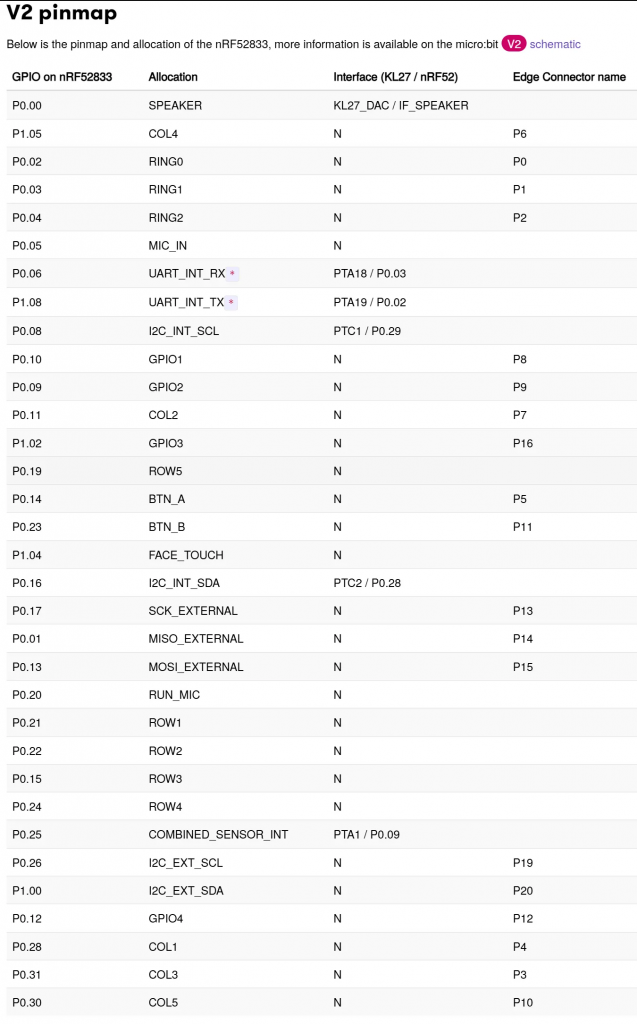
https://tech.microbit.org/hardware/schematic/#v2-pinmap
This is a link to my Git repo since the code is getting quite large.
git: https://github.com/OskeLTU/Zephyr_code
Here i have gotten the car to drive but without the pwm controls for now. I have plugged the pwm to 5v to just keep it at 100% at all times. otherwise everything works as intended. My first try and the part that led me to success was getting a led to glow
video for led: https://youtu.be/bUXijsHoW68
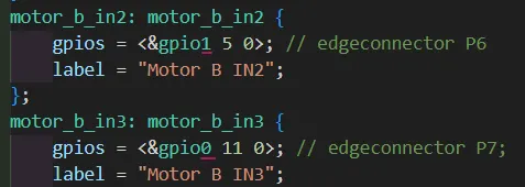
here i finally cracked the code on how to setup the GPIO pins for zephyr to accept them. Then using the mapping for the microbits edge connectors i distributed the pins accordingly
i was also a bit lost when it came to the rings and had some issues where only three of the wheels would spin even though the code was perfect.


So when i saw the issue i corrected it and everything went smoothly
video for car driving: https://youtube.com/shorts/cgm4MP-XxX8?si=8Dxuh2RRsCdfTP10
Everything went acording to plan last week. My next course of action is setting up the pwm controls for the car aswell as making a “library” for motor controls where the start is allredy posted on github under “working” tree
https://github.com/OskeLTU/Zephyr_code/tree/working/Driving_car/src
Øivind
“Dual understanding of Space”
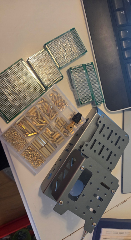
By that I mean both outer space considerations, and the physical size and viable size of components on the rover. Luckily I know that most of the parts I plan to use, come in smaller and denser options, but with the same functions. I will make the electronics configuration in a manner that I can scale down and change components when I hit obstacles in the design. My current plan is to solder onto prototyping PCB’s. This will give people with the needed knowledge a quick understanding and fast way to implement into a more feasible construction.
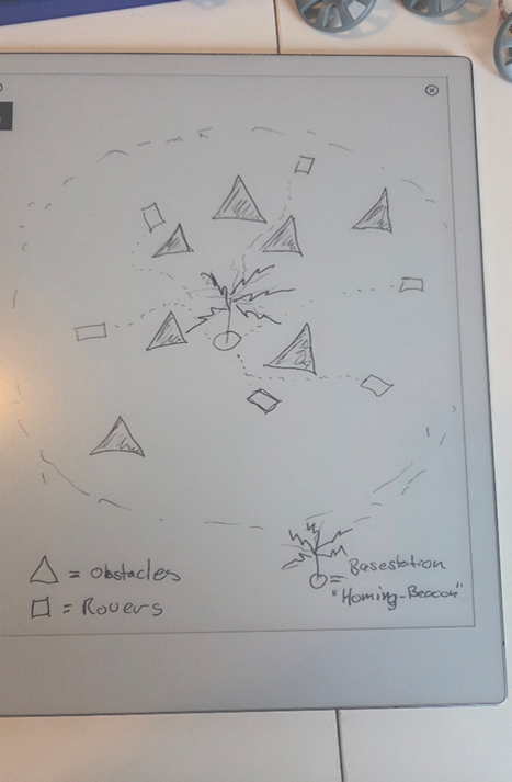
Working on setups for a “Homing beacon” for the rover. A signal the rover can pick up and use for help to return to the base. An option is to use a system similar to Instrument Landing System (ILS) when the rover is close enough to have a free path directly to the base where it can charge, dump samples and such.
Reading about options several is interesting, but after last drawing I might need more than one option.
I’m looking into AprilTag. Seems like this is one of the technologies I was thinking of, and that it exists.
Now I work towards a solution where I can get the rover to actually charge when home, or stick a RF tag to it and connect a buzzer to the base-station. If connected, that will be an indicator that the rover is at least is close to its dedicated module at the base f.ex charging station.
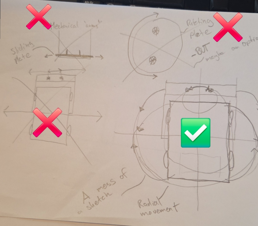
Since Mecanum wheels is a bad option on the moon, the sideways “whole car” adjustment on my former mentioned drillbit and sensor on the rig, an azimuthal rotation will be better. This will minimize the need for movable parts on the rig. After reading about lunar dust, a sideways sliding plate is out of the equation. But a carefully crafted setup and use of rota tion might be a viable option.
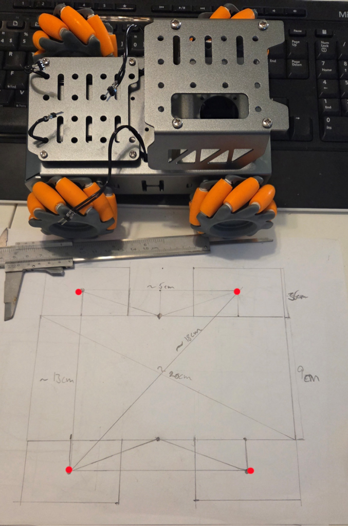
Measures of the car and analyzing the equilibrium point so I can take that into account when the components is to be mounted. Some equipment is also going to be implemented outside the rovers quadratic wheel setup, and its body rectangular perimeters. Equipment with different overhangs will affect the total balance of the rover.
Later I will need to take account the total volume when I stack and alter the height of the rover.
Moons Gravity = 1.62m/s^2 which is about 16.5% of the gravity on Earth. There are pros and cons about that.
Moon diameter = 3474200 m => Surface Area +- 3.793e1013m^2 => Volume +- 2.195e19m^3
Verifies that I have got the right number of protoboards, but not quite the right type and size. But I will be able to work with these anyway.
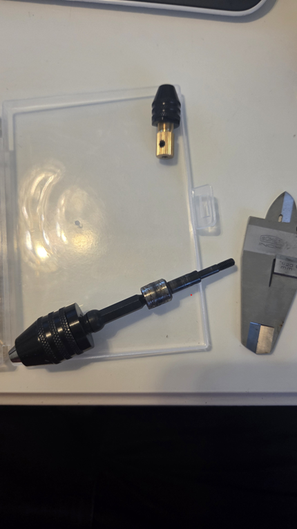
The picture to the right shows a system for the drill function. I hope that I can get that with quick coupling at both ends, so that it will be easy to assemble and disassemble if needed. What kind of engine I should use is still uncertain. I have read and checked what I should have for a good system, but possibly I simplify the actual drilling function on this prototype.
Very little of “micro” in this project, even though my subject is microelectronics, except for the use of micrometers, and capacitors marked in microFarad. As mentioned before, this is intended and also a byproduct of me not taking the “Elektronikkonstruksjon” class. I want my modules to be swappable to other projects later when I need more opportunities for a cost so low that I can experiment without risking high-value equipment to burn
Finishing off this blogpost with slight disappointment that I am stuck at some features. But I will try everything possible to manage most of my plans.