Sondre:
This week, I focused on improving the reliability of the sensors on the robot and integrating the IMU to achieve accurate direction tracking. To make this work, I had to modify how the robot handles turning, including adding calibration routines and smoothing of sensor readings. These changes made the robot’s movement more stable and its navigation more consistent, especially when performing 90-degree turns.
IMU:
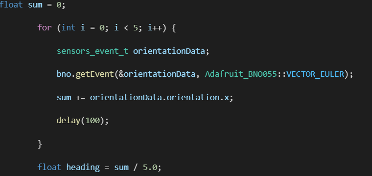
To integrate the IMU with the robot’s movement system, I first had to make the start_heading value reliable. This is crucial because all turns the robot performs during the course rely on this initial heading. To achieve this, I implemented a simple calibration sequence when the robot starts. The code takes multiple readings from the IMU and averages them to reduce sensor noise and fluctuations:
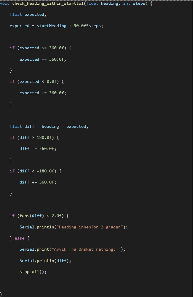
The robot then uses the start_heading as a reference to compare against its current heading after each turn. Since all turns in the course are 90 degrees, the new heading should always be start_heading +/- 90 degrees or start_heading +/- 180 degrees, depending on how many consecutive turns it has made in the same direction.
To keep track of this, I introduced a variable called turnDirection. Every time the robot turns right, this variable increases by 1, and every time it turns left, it decreases by 1.This allows the robot to calculate what its expected heading should be after each maneuver.
At this stage, the robot can now keep track of its orientation between turns and detect if it has deviated from the intended direction. I still need to implement automatic correction after each turn, but I did not have time to complete that part this week as I was away from Thursday.
I still had to integrate the IMU into the 90-degree turn functions.
Up until now, the turns were done with a timer, meaning the robot would rotate for a set duration using delay() to estimate a 90-degree turn.
This method was inconsistent because factors like battery level, surface friction, and motor calibration could cause the turn angle to vary each time.
To fix this, I modified the turn functions to use the IMU and its readings.
Instead of relying on time, the robot now reads the heading in degrees from the IMU during a turn and stops once it reaches the target angle.
This ensures that every turn is as close to 90 degrees as possible, regardless of external conditions.
Below is a video with the robot turning right with the new logic:
https://www.youtube.com/watch?v=Njt-LEgV4r8
And as you can also see in the video. If it does not stop exactly where it should it corrects. This is done by having a condition in the main logic. If the scene is clear and the heading is of by more than 5 degrees, it corrects a bit in the other direction.
This week I did not get to do all I wanted since I went away and there is still a bit to do. I have received motors with encoders. I would really like to integrate this into the system. But this would mean changing out the Micro:bit for a microcontroller with more interface pins. It would also mean that we need to have motor controllers and a different battery system than what we currently use. Even though this would be ideal, it might be more work than what we have time for. So, we will have to see.
Next week I will need to change how the robot sences if it is centered on the course, by combining the heading reading from the IMU with the ultrasonic sensors. I would also like to look into what would need to be changed by upgrading to the new motors, both hardware and software.
Robin:
Week 9 was dedicated to the detailed study of the robot’s power supply system.
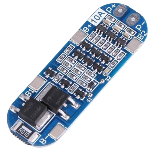
My research highlighted the necessity of integrating a Battery Management System (BMS) for using Li-ion batteries. The BMS is essential for two main reasons:
- Protection: It protects the batteries against voltage spikes and excessive discharge.
- User Safety: It allows for recharging the batteries without risk to the user.
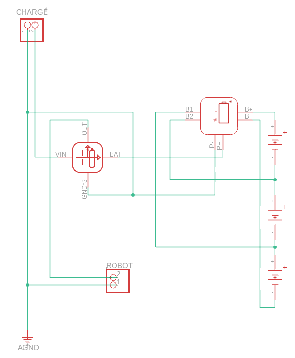
Components and Wiring
Wiring Diagram of the power system integrating the batteries and the BMS:
Anette:
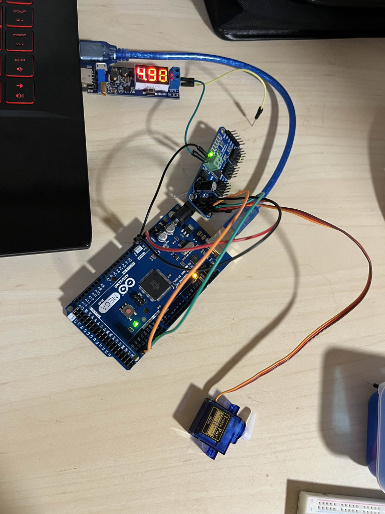
This week has again been a bit busy due to an assignment in “Reguleringsteknikk 2” that I also had to work on. Despite this I did finally get to test the servo controller board (PCA9685) with a servo motor. I started by testing the servo motor itself with a basic code on the arduino mega, before connecting the board to test it. I only have one motor and we are going to use 2, but this should easily be implemented. I borrowed the power supply module from Sondre which made the testing easier. I did notice when testing the module that the power output didn’t match the value I got on my multimeter, but it was not far enough off that it made a difference.
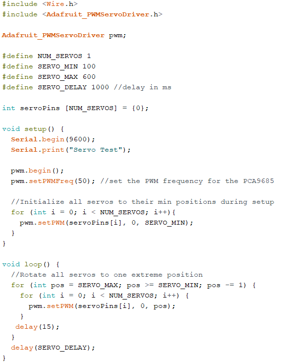
I also used this code to test the motors:
Furthermore I have also been doing a bit of research towards the bms system. Until now there has been some uncertainty regarding the power supply we were going to use. We were advised in the beginning to use 3 x 3.6V Li-ion batteries, but since then we haven’t heard anything, so we decided earlier this week to order the batteries. Until now we have been using a power bank in order to test the car, so it will be nice with a more practical and permanent power solution. Since we decided to use these batteries we need to make a battery management system (bms). It’s important that we finalize a solution for this by the end of the week due to the time issue with ordering pcbs and other components.
Matias:
This week, I’ve nearly finished the PCB design. The only things left to complete are the ground plane and the mounting holes, so the layout is almost ready for production. It’s been great to see everything coming together after all the planning and schematic work.
After discussing with Steven, he suggested that I start looking into active filters, which I will be including in the PCB. I’m currently researching how they work and how to implement them effectively in our design. It’s a new topic for me, but it’s interesting and directly relevant to improving the performance of our system.
I hope to finish everything by the end of this week at the latest, including both the final PCB touches and integrating the active filters. This week has been a mix of completing practical work and exploring new theoretical concepts, which makes it feel productive and engaging.
Théo :
This week I finalized the calibration of the 2 servo controlling the arm and fixed it.