Åsmund Wigen Thygesen
This week was going to implement the “set motor speed” functions. With the motor controllers we are going to use we can use PWM to control the motor speed. However, when looking into using PWM with the raspberry pi I have found little official specifications on the PWM capabilities of the raspberry pi 5, outside of official channels I have seen varying and sometimes conflicting information.
From what I did manage to find it seems like by default the gpiozero library uses software PWM, which would potentially be inaccurate under load, and we need the PWM to be pretty precise since we want to control motors and servos with it. You can change the pin factory, and the pigpio factory, from what I understood, is supposed to utilize hardware PWM, but I failed to find information on whether applies to all pins, just some pins, or any pins but a limited number, so to be sure I decided to do some testing before implementing anything.
As far as I’m aware, we need 4 PWM signals, tho not all are required at once, so for testing I decided on running 5 simultaneous PWM signals, where 2 of the pins are marked as PWM in some pinouts and the other 3 are not. The duty cycles were set to 0.8, 0.65, 0.5, 0.35, and 0.2 all different in case there’s an optimisation for identical PWM signals.
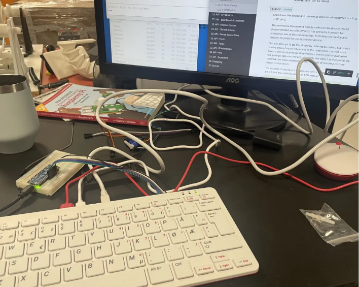
To measure the signals I would normally have used an oscilloscope, but didn’t have one at hand. Instead I utilized hardware interrupts on an arduino nano every(newer version of the nano, which is interrupt capable on every pin). Tho due to memory limitations I ended up having to sample just one signal at a time anyway.
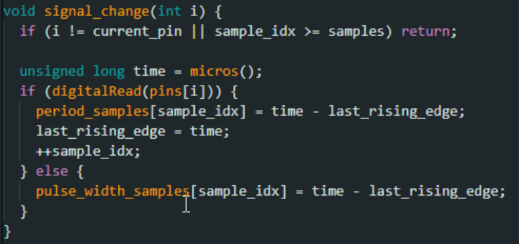
This is the sampling function, it is called from each interrupt service routine, with the associated pin index.
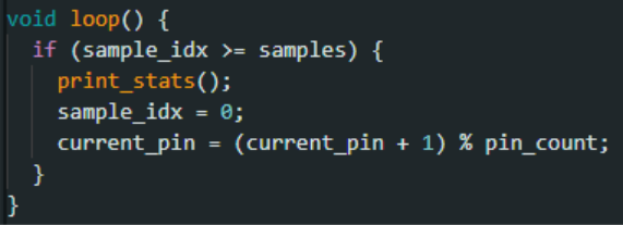
This is the loop, pretty simple, just prints the stats, resets the sample index and increments the pin currently being sampled. The print stats function calculates the average and standard deviation of the duty cycle, pulse width and period.
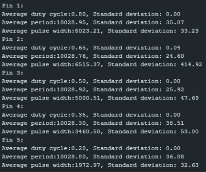
With that in place I first tested the default PWM without anything else running on the pi, already this was pretty inconsistent, the screenshot below is one where the signal was pretty good, but I had lots of variation even at low load probably due to background programs.
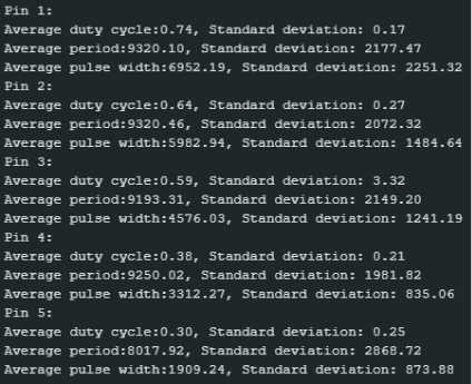
When testing under high load the PWM was consistently very bad, to the point it at times broke my sampling method, as you can see for the pin 3 readings below, where the standard deviation for the duty cycle is 3.32, which seems a bit off considering you can’t have a duty cycle greater than 1 or less than 0. I have some suspicions of how that happened, but it’s hard to say for sure without an oscilloscope.
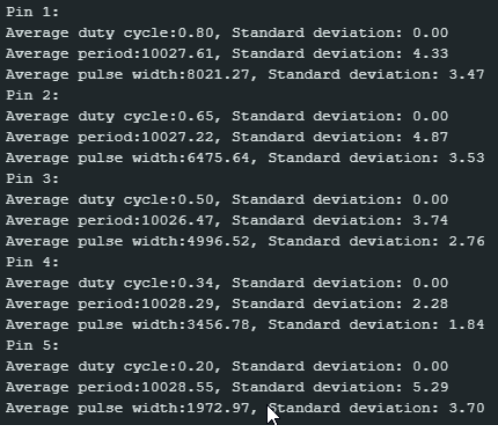
When switching to the pigpio pin factory things immediately look at lot better, for all pins. The image below is the data under low load.
Then under high load the average and standard deviation is essentially the same, so this at least shows we can use the raspberrys PWM, we just have to change the pin factory.
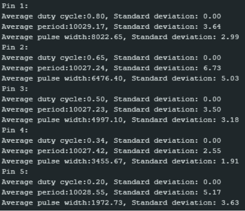
In conclusion, it my testing does indicate that the default PWM for the gpiozero library is indeed software PWM, but we can use the pigpio factory for what seems like hardware PWM on at least 5 pins, it’s at least consistent enough for our purposes.
I found the testing very interesting, but it did take a lot more time than anticipated, so I didn’t get time to do anything else, but at least a potential pain point has been eliminated.
Sulaf: Obstacle Avoidance
This week, I continued developing my obstacle detection module and began implementing basic obstacle avoidance behavior. Last week, I focused on setting up the detection system — using threading and shared flags to monitor sensor input independently of the navigation system. This week, I expanded the module to include a simple avoidance maneuver that can be triggered when an obstacle is detected.
The goal remains the same: to create a safety layer that runs in parallel with the navigation system. While the Raspberry Pi only has one core, threading allows the detection and avoidance logic to run in a way that appears concurrent with navigation. This means the robot can continue searching for weeds while also reacting to nearby obstacles.
Integration Strategy
Since I still don’t have access to the navigation code, I designed the module to be fully independent. It runs in its own thread, continuously checking sensor input. When an obstacle is detected, the module:
- Sets a shared flag (_is_blocked = True)
- Interrupts motion by stopping the motors
- Executes a basic avoidance maneuver (e.g., turning slightly)
- Resets the flag once the path is clear
This behavior is testable without needing the navigation system. Later, the navigation module can read the shared flag and decide whether to pause, reroute, or resume movement.
Software & Hardware Used
- Ultrasonic Sensors (for front, left and right detection)
- Digital GPIO pins for the Raspberry Pi for sensor input
- Motor Control Interface (shared with the navigation system)
- Compass and Wheel encoders (used indirectly for orientation and position)
Testing Setup
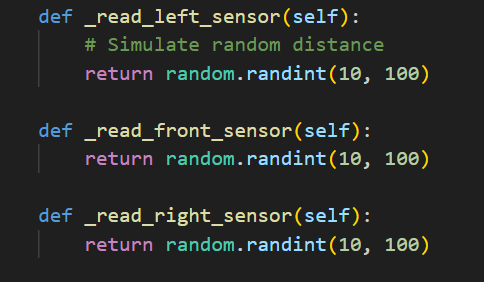
Because I still don’t have access to the physical robot or sensors, I continued using simulated sensor readings. These are randomly generated values that mimic ultrasonic distance measurements. This allows me to test the logic and structure of the code without hardware.
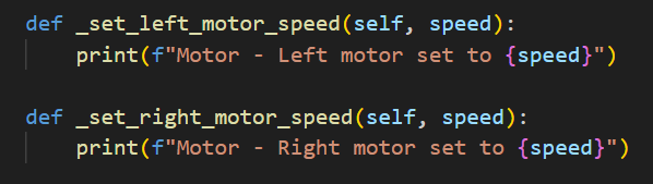
I also added simulated motor control functions that print actions to the console. These will be replaced later with real motor commands from the navigation system.
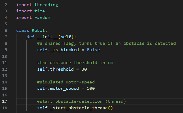
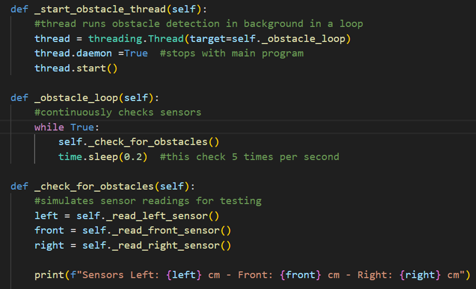
I continued to use the python class that will declare/define the shared flag, the distance threshold and obstacle detection in parallel (threading):
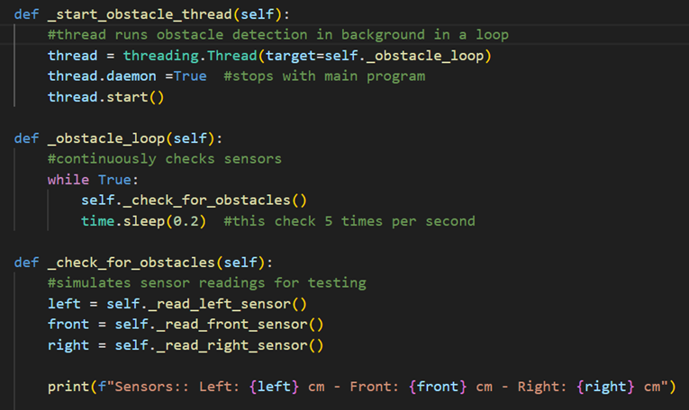
And the obstacle detection will also be continued to be used:
Obstacle Avoidance (New)
Since this week focused on obstacle avoidance, that is what this new code tackles. Obstacle avoidance is essentially navigation when obstacles are detected, ergo navigating until all sensors are giving the clear. That is why the sensors are always being read as before. To make this possible, I have to move the car by manipulating the motor speed.
Again, reminder that this is the navigational part, and since I do not want to infringe on Åsmund’s part, and since I do not have a physical car model in my possession to even test this, I opted for printing out the navigation/turns. This is easy to change out anyway, and does not affect the obstacle avoidance at all. This is efficient for testing.
Emergency Stop and Obstacle Avoidance (Integrated with Obstacle Detection)
As a reminder, with the obstacle detection I made last week (the threading, the detection loop and the constat checking for obstacles):
And thorught the updated flag I made:
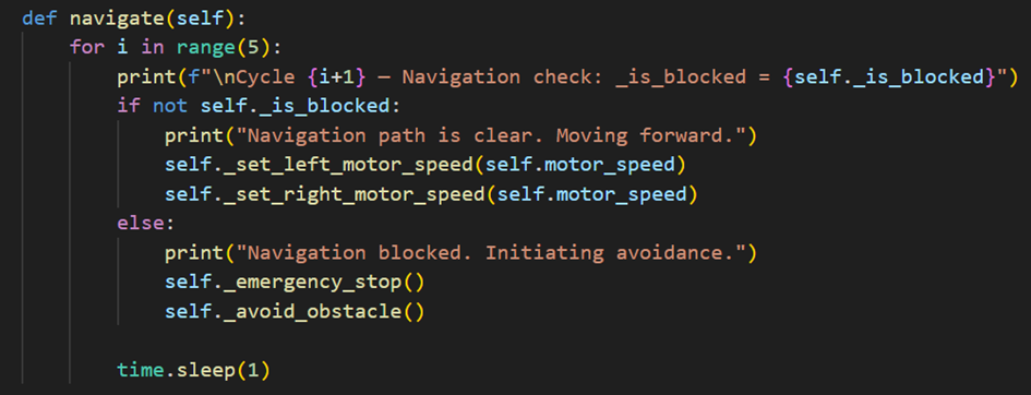
I can now monitor the obstacles with sensors and check if not self._is_blocked happened or not, if no obstacles are detected through the obstacle detection system, then it will move forward, or else it will ‘emergency stop’ and ‘avoid obstacle’ (a new feature, obstacle avoidance part). So now I have to make the emergency stop and avoidance code, which turned out:
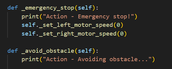
This block is the part that stops all navigation when an obstacle is detected by setting the motors to 0. The function below it, the _avoid_obstacle, is simply included to showcase in the terminal better what the system is doing for clarification and testing.
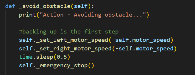
Now that I have the stopping functionality, I still need the navigation method to maneuver around the obstacle. Last week I only had an indicator in my _avoid_obstacle function, I expand this week to include actual navigation. This navigation would include backing up:
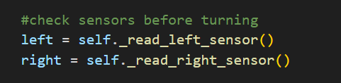
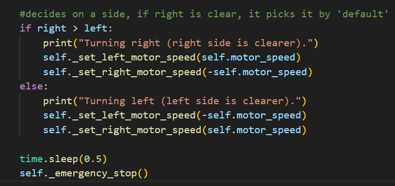
Then the sensors check which side does not have any obstacle:
Following, it maneuvers out the way:
Then lastly it does a final sensor check to update the shared flag, to prevent blind movement (and collision), and to confirm the maneuver was a success. All of these functions are inside of the _avoid_obstacle() function.
Testing
I stimulate this in the code by changing the navigation code from last week, since I noticed that no matter if there was an obstacle detected or not, the avoid_obstacle function was not triggered properly. The issue is likely due to how fast and randomly the simulation runs. The sensors generate random values every 0.2 seconds, so the flag flips to false and back before I can even notice. I realized that due to the mismatched timing and the many loops that I have, it’s hard to get the avoidance function to trigger. Thus I changed the navigational cycle:
Output
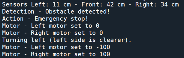
Here it is possible to see the navigation when an obstacle is detected, by manipulating the motors, either turning them right or left. The cycle in which it detected an obstacle with the sensors is also included.
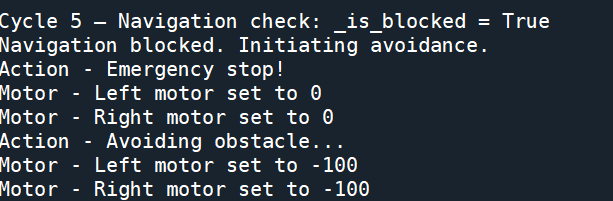
As you can see, the obstacle avoidance code works, and as it the obstacle detection did, this should also be able to run in parallel with the navigational module in with thread I used.
Integration with Navigation Module
I still have to keep this part in mind, however, seeing the update will not affect the navigational part, thus the only thing he needs to do is import my class and check the flag before letting the robot move. In the testing part I used:
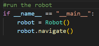
Which runs only if the file is executed directly. It prevents the code from running in when the file is imported as a module, so he can reuse my Robot class without triggering navigation automatically.
Rick Embregts
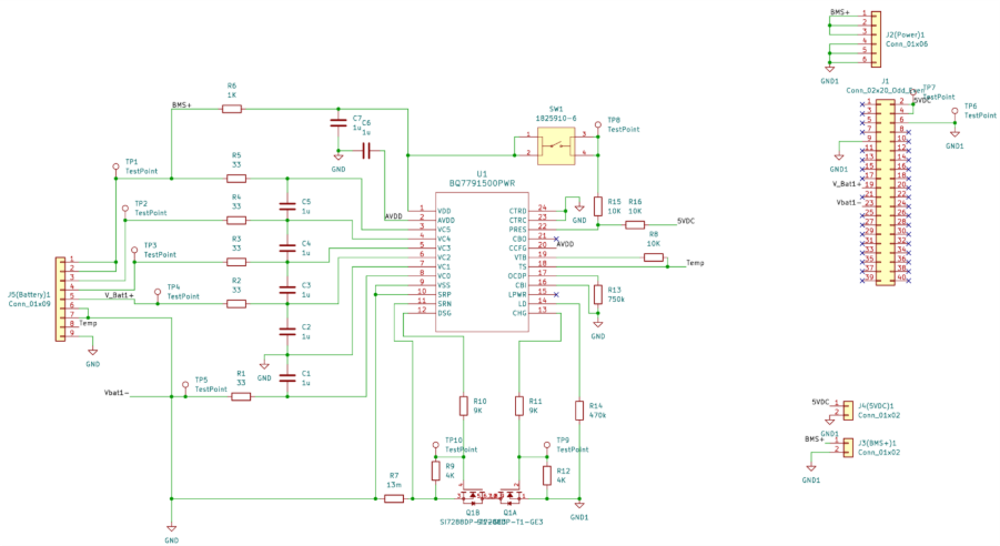
In the following text the main design of the Motor Control Unit and the Battery Management System is explained. At the end of this segment you will find the pictures with the full schematic.
MCU
- Protection
The limits of the motors are mainly determined by the thermal energy the motor can dissipate. Since the biggest factor in the thermal energy is the current the motors can be current controlled by the jumpers from connector J5
- Current measuring
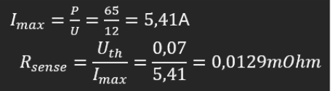
For allowing the DRV8840 to mesure the current flowing through the motor the schematic includes a resistor of 82mOhm connected between Isen and ground.
Calculation of current measuring resistor:

With two 2 resisters Vref is set to be 1V. Ichop is calculated by with the max amperage the motors can handle times 2 so we can drive 2 motors with one driver.

According to this equation the resistor Rsense must be able to dissipate 0,472W.
- Other functions
The DRV8840 Also has sleep mode, Fault detection, reset, Drive, Direction and decay inputs and outputs. The pins of sleep mode, decay, fault detection and reset are bridged between the 2 controllers for the left and right motors to take up les pins in the raspberry. The other pins have a sepret connection to the Raspberry. All pins can be connected directly to the raspberry due to the internal logic of the MCU functioning from 2VDC.
- Spray motor
To control the motor that sprays liquid a relay is used in combination with a diode to protect the raspberry from the induction of the coil in the relay.
- Heat dissipation
Since the current is flowing through 2 mosfets at almost every time the calculation for the generated heat is as follows:
Even with the highest thermal resistance of 31.6 C/W the chip will stay below the specified operating temperature of 86 C up to a ambient temperature of 37,75 C. The real thermal resistance will be far below the above mentioned resistance. Therefor I comfortably conclude that the chip is adequately cooled and there is no need for some sort of heatsink.
BMS
- Battery connections
For the battery connections I copied the design used in the datasheet for 4 cell with internal cell balancing. This reduces the cost and costs less time. The downside is the lower balancing current. However this is not a problem since the imbalance between the cells should not take too long to discharging the cell with 50 mAh.
- Battery protection
The battery is protected by a sense resistor. Pins SRN and SNP are connected to both ends of the resister to mesure a voltage. If this voltage is above 70mV than the protection kicks in. The protection time is set by resistor R13 to the maximum time of 1,4 seconds. For short circuit the time is lower.
See the maximum allowed current and corresponding resistor R13 (Rsense) calculated in the following equation:
- Temperature sensor
The specified temperature sensor is the 103AC NTC and is a cheap widely used temperature sensor perficly suitable for this project. The circuit’s described in the datasheet also operate with this sensor which means I can copy and paste this part as well. The only modification is that there will be a connector for the NTC on the board instead of a soldered NTC.
- Battery connection
Due to the limited current capebilities of the battery connector the decision is made to double the ground and positive whire by making the connector 2 pins larger. This saves cost for a new connector an simplifies the PCB.
- Low power mode
The BQ77915 from texus instruments has a hibernate mode. In this mode the current draw of the chip is reduced to 2 micor amps. To wake the system up a power switch is connected to the press pin with a 10Kohm resistor. When this is pressed the raspberry supplies the 5V needed to keep the BMS from entering hibernate mode. To enter hibernate mode the entire battery has to be disconnected to make sure the raspberry is not supplying the press pin.
- Mosfets current paths
There are 2 mosfets in the recommended schematic. This is to make sure that the battery can be charged when depleted and discharged when full of charge. Both mosfets are connected through the pcb by drain like the recommended schematic. To calculate the gate resistor see the following equation:
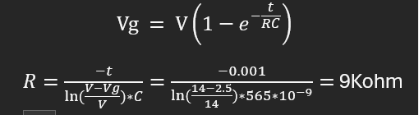
According to the datasheets the input capacitance of the mosfet is around 565nC and the supply voltage to the gate around 14V. Since the minimum gate voltage is 2,8V, we can conclude that at is 1 the voltage at the gate is already around 8.8V so above the minimum gate voltage. Therefor we can calculate the resistance by changing the
so we come to the decided 1mS of turn on time. This time is not based on anything and is just a random picked time since the mosfet will turn on and off at way above 1Hz frequency’s. Therefor the switching losses are not calculated.
- Mosfet pull down resistor
Since the supply voltage of the gate driver of the BQ77915 supply’s 14V the pull down resistance can be calculated by the following formula.
To discharge the gate as fast as possible and keep the gate voltage at a minimum of 3V the lowest possible resistor value is 4Kohm. Choosing a higher resistance will result in slower turn off time. Choosing a higher resistance will result in a lower gate voltage and will therefore not allow enough current flow or generate higher losses.
- Grounds
Since the current path is broken at the negative therminal it is neccicery to not connect the BMS chip and the raspberry to the same ground. Otherwise the mosfets will be bridged and useless so the BMS can’t cut the current flow through the battery. The input of the raspberry’s however are still connected to the BQ77915. In lots of cases this is absolutely not ideal. But since the voltage across the mosfets will be verry low it poses no risk to the inputs in the raspberry.
MCU
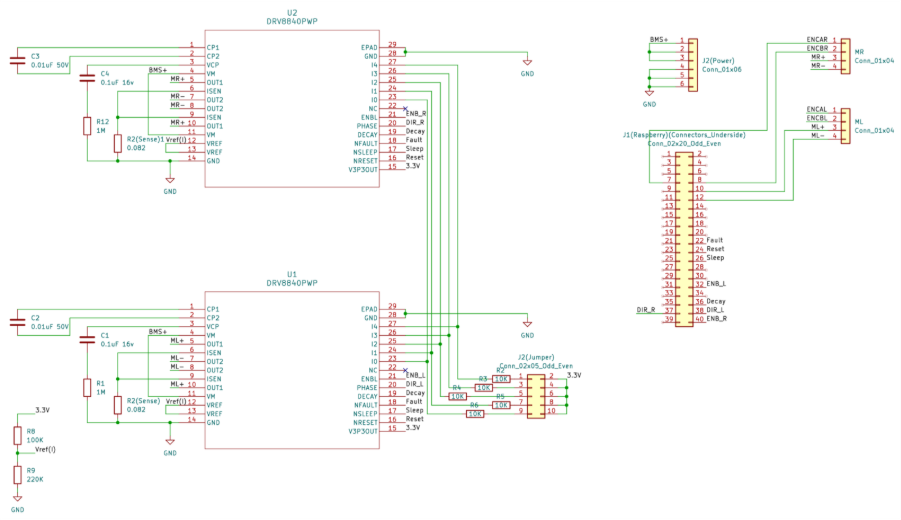
BMS