Bram van den Nieuwendijk
This week I had a discussion with Richard about the feasability of my design and any possible improvements. I spoke with Steven about the possibility of making a pump myself instead of ordering one. If that doesn’t work out, the pump is in stock with a lead time of about one week, so I can still fall back on that option. The step for next week is to have the design finished so that the building process can start.
Darkio Luft
After the presentation I met Steven and discussed about the image recognition system, He showed me about the Image segmentation and how this can improve the results of detection and also being able to track the weed during the detection, I started searching how to implement this in a new model to see how it works.
Rick Embregts
All of the schematics and PCB designs are finished and submitted to order. In the immages below is seen what the schematic of the BMS looks like and what the PCB’s look like.
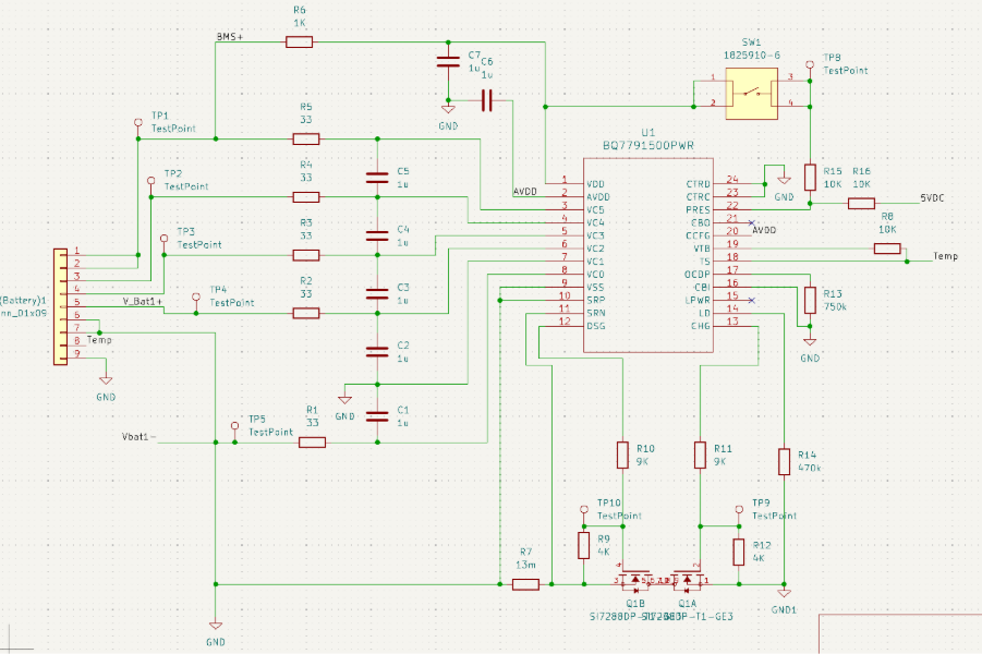
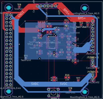
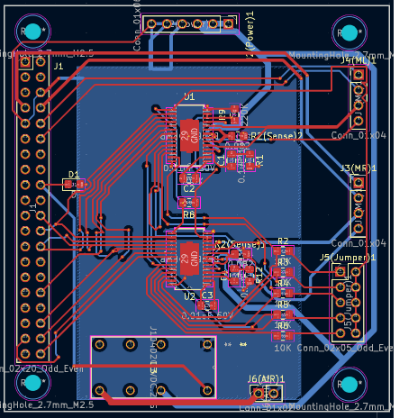
Next week the tests will be done together with a written explanation of how the schematics work.
Åsmund Wigen Thygesen
This week I continued work on the motion control system. Currently we have rotation of the vehicle, and some setup parameter, we need to keep track of where the vehicle is. To achieve this we use the encoders in the wheels, since we know how far each wheel has moved for each step of the encoder and have the angle of the vehicle, we can figure out how far along the x and y axis the vehicle has moved.
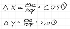
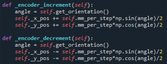
These equations give us the change in x and y position for each step along angle theta. To implement this we just add or subtract the change in x and y to the x and y position respectively. Then since we have 2 wheels and 2 encoders, we divide by 2, this is not a perfect solution and needs to be improved if we want to do movement other than driving straight forward and turning.
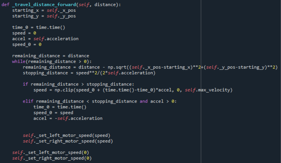
Now that we know the vehicles position, we can implement driving forward a set distance. Which is rather simple, we store the starting position, then drive both sides forward until the distance to the starting position is the same as the distance we wanted to travel.
However, to avoid the starting and stopping being abrupt, we need to be able to set the acceleration so the speed is gradually increased, rather than full speed immediately. For simplicity we will operate with a constant acceleration for speeding up and slowing down. We also define a max speed.
With the vehicle needing to slow down gradually before stopping, we have to figure out the total stopping distance, for which we can use one of the formulas for movement under constant acceleration.
Tho we can simplify a bit, when accelerating V_0 is 0 and when decelerating V_0 would be the current speed and V would be 0, while acceleration would be negative. Meaning we can just use S=V^2/2a the whole time.
The velocity is simply V=V_0 + a*t, so we need a timestamp when acceleration started. Then, so long as the remaining distance is greater than the stopping distance we update the speed, capping it at our max velocity parameter. Once the remaining distance is less than the stopping distance we reset the time, set V_0 to our current velocity and invert the acceleration.
This acceleration should also be implemented for the rotation of the vehicle, as it previously just starts and stops the motors at max speed. In principle it’s much the same, but we need calculate the remaining distance and stopping distance a bit differently since we’re rotating instead of driving in a straight line.
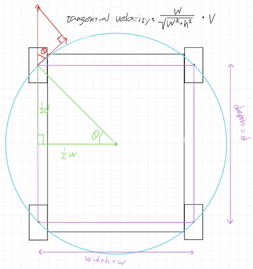
This is an approximate drawing of the wheel layout, specific dimensions aren’t really important for now. The blue circle passes through the center of each wheel and is the turning circle assuming uniform wheel slipping. We get the turn diameter by taking the diagonal of the “wheel rectangle”. The component of the wheel speed along the tangent of the turning circle ends up being just the centre to center width of the wheels divided by the centre to centre diagonal
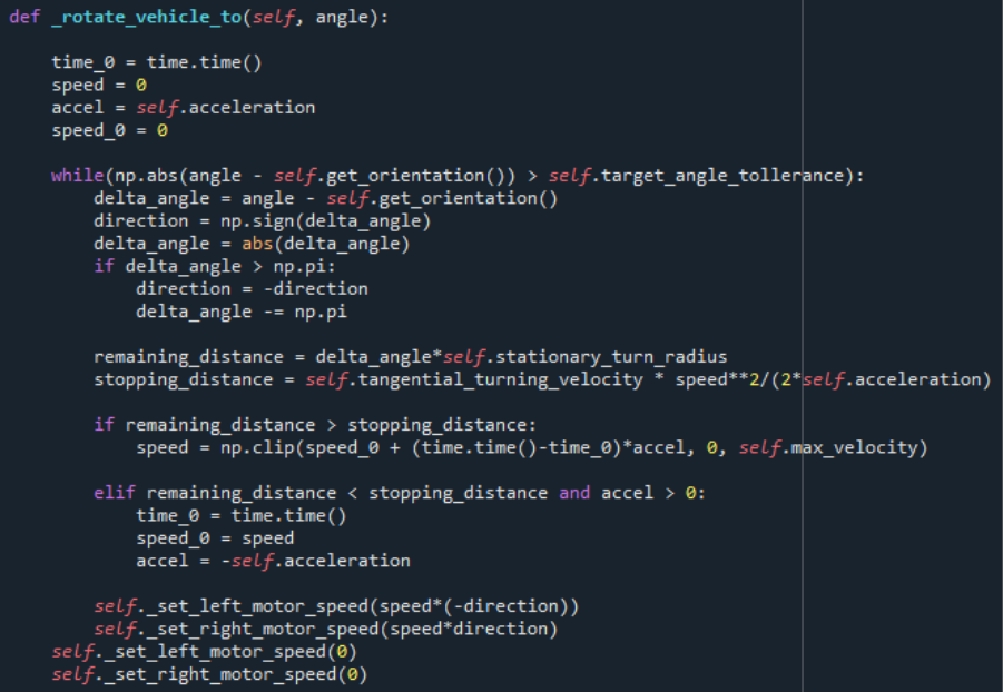
When implemeted we get something very similar to the moving forward function, the main difference being the remaining distance and stopping distance calculation. Also the stopping condition being slightly different, so it can turn back again if it overshoots slightly, as overshooting the rotation will most of the time result in greater error in final position than overshooting the distance slightly.
Sulaf: Obstacle Detection
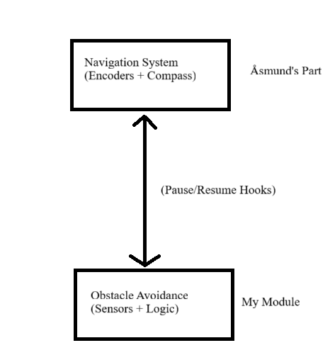
This week I focused deeper on obstacle detection. While the navigation and motion control system was handled by another group member, my module operates as a safety layer that runs in parallel and ensures the robot can detect and avoid obstacles in real time.
The entire idea behind this is to somehow make it run in ‘parallel’ with the navigation system. It will not actually be parallel, since we only have one core in the Raspberry Pi, but it will appear as such while the robot is moving: searching for weeds while also keeping an eye out for the obstacles around.
My module is designed to run independently of the navigation system, using a continuous loop or thread to monitor sensor input. When an obstacle is detected, it:
- Interrupt the current motion (e.g. stop motors)
- Trigger an avoidance maneuver (e.g. turn slightly, back up, or reroute)
- Resume navigation once the path is clear
My obstacle detection and avoidance is slightly reliant on the navigation, however in this manner I only need a few hooks from the navigational system:
- A way to pause or stop the robot
- A way to resume movement or send a new target
Software & Hardware Used
- Ultrasonic Sensors (for front, left and right detection)
- Raspberry Pi
- Python
Sensors Implementation Code
To avoid waiting for the navigation code, I considered these options:
- Callback functions: where one module calls a function in another
- Shared flags: one module sets a flag and another reads it
- Threading: runs code in ‘parallel’ with navigation
My initial thought was to use interrupts, however that would not be able to be implemented on the raspberry pi we have.
Method
I decided to go with the shared flags system with threading because it is easier to implement throughout several modules, assured integration between the navigational and obstacle avoidance system would be guaranteed. This method is also more independent: I can work on my part without needing access to his loop.
If the navigational system and the obstacle detection system ran in the same ‘while True’ loop (a continuous loop that checks the sensors, moves the robot and reacts to obstacles), then a shared flag system would be sufficient. But since I do not have access to the navigational code yet, and since his code is likely running in his own loop, and I am to run and test my obstacle detection independently for now, I included threading, so obstacle detection is completely independent from the navigation module.
Code (obstacle detection)
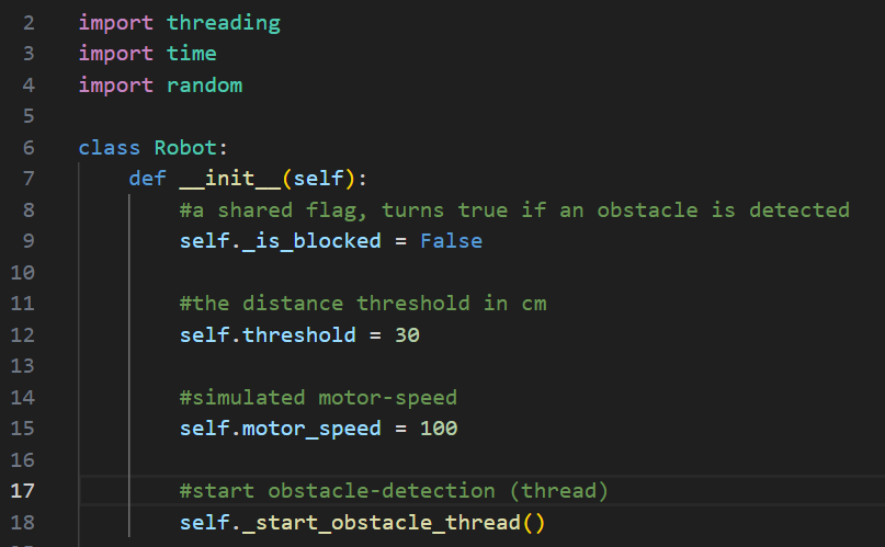
I first made a python class that will declare/define the shared flag, the distance threshold and obstacle detection in parallel (threading).
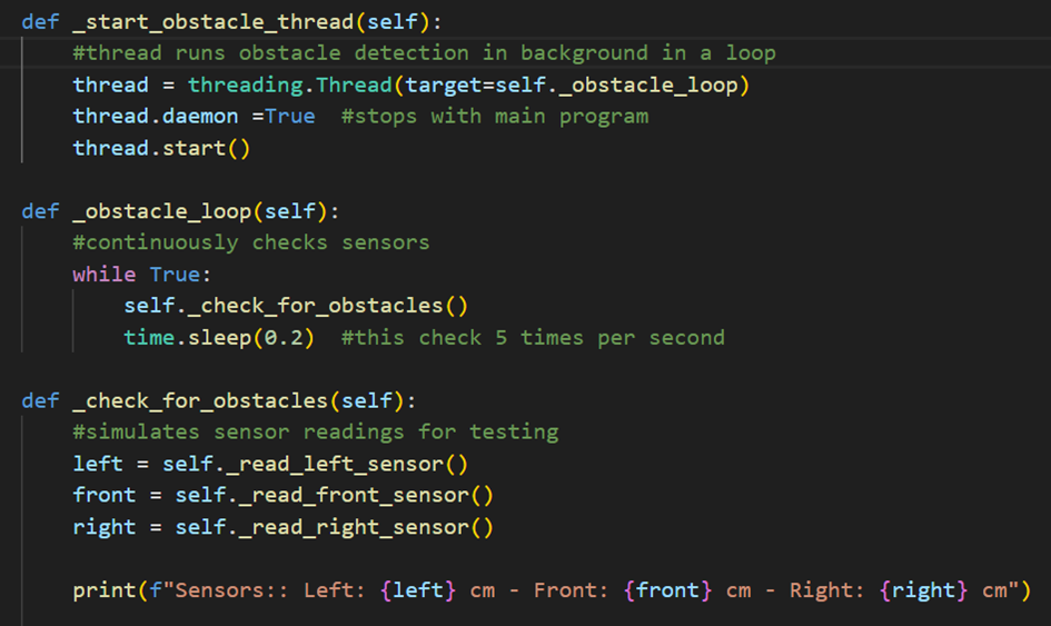
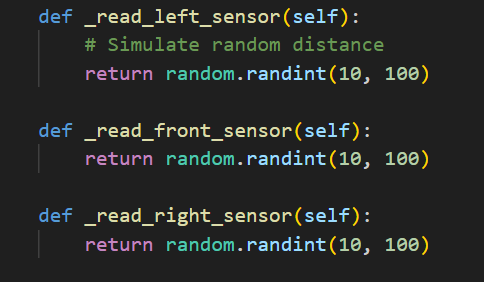
For the obstacle detection part I defined the obstacle loop so it checks the sensors at all times (5 times per second). This allows continuous monitoring, efficient. I read from the sensors that I defined, one for the front, and one for each side. In short, I initiate the thread for it to run in parallel, then make an obstacle loop, following up with check for obstacles from the three sensors, and print out the distance for each sensor.
It is important to note that we are yet to 3D print anything, and I don’t have access to that car as if today, so to overcome that obstacle that has truly hindered me from doing much coding so far, I decided to simulate those senor readings. I can do this because this in the end will not affect how the code works, it is used to see if my code works.
Simulating sensor inputs
As mentioned above, these are simply used as a substitute for sensor readings to test if the code works as, it should, detecting obstacles.
So far I have made the thread, the obstacle detection running in a loop checking for the sensors, and can test it with simulated sensor readings. However, I still need to think about how to integrate this with the navigational module. That’s where the shared flag comes in, and to implement that I need updated sensor readings.
Running and Testing for Obstacle Detection and Sensor outputs
I ran a test using:
Output
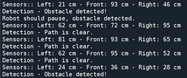
As you can see, the obstacle detection code works, and should be able to run with the navigational module in parallel since I used threading.
Integration with Navigation Module
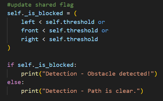
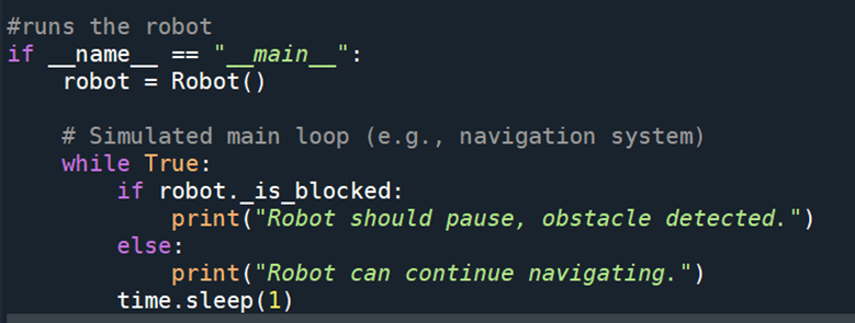
How will the navigation code integrate with mine, vice versa: the way I have set it up, the navigation code can run independently in it’s own loop, however, before it’s initiated it always checks my flag robot_is_blocked, and if it’s true, it stops and waits. I tried to find the easiest way to integrate my module with his, and so I figured that the only thing he needs to do is to import my class, create an instance/object of my class and check the flag before letting the robot move.