Hello and welcome back!👋
We’ve officially started Sprint 4, and the project is really taking shape. This week, much of the focus has been on development and testing across different parts of the system – both in hardware and software. This is what our team members have been working on.
Fredrik:
This week we started sprint four, which means we should be nearing a working product. Now that the arm structure is in place, we need to get the hydraulic system fully working and implement it.
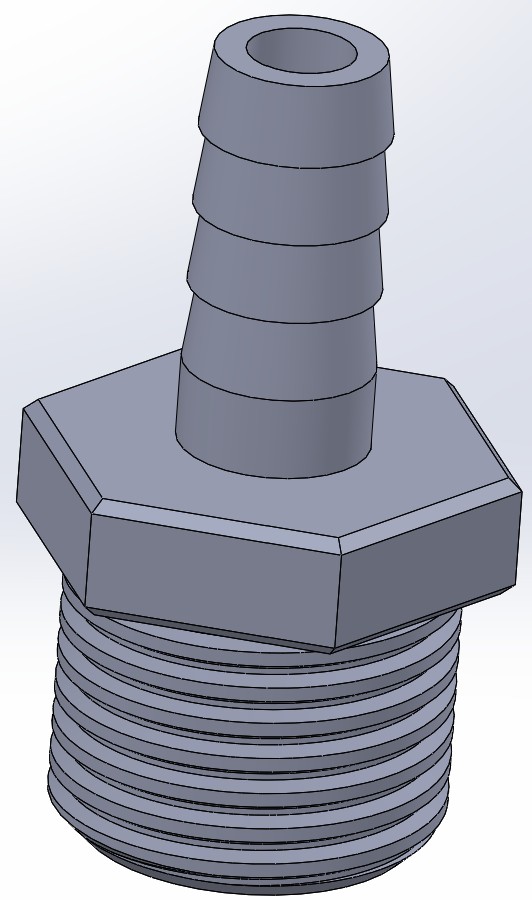
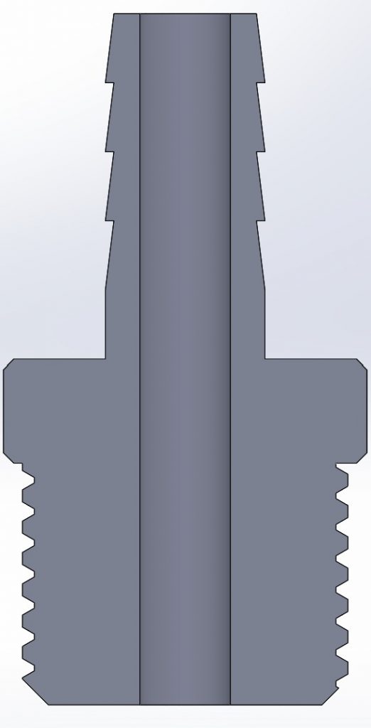
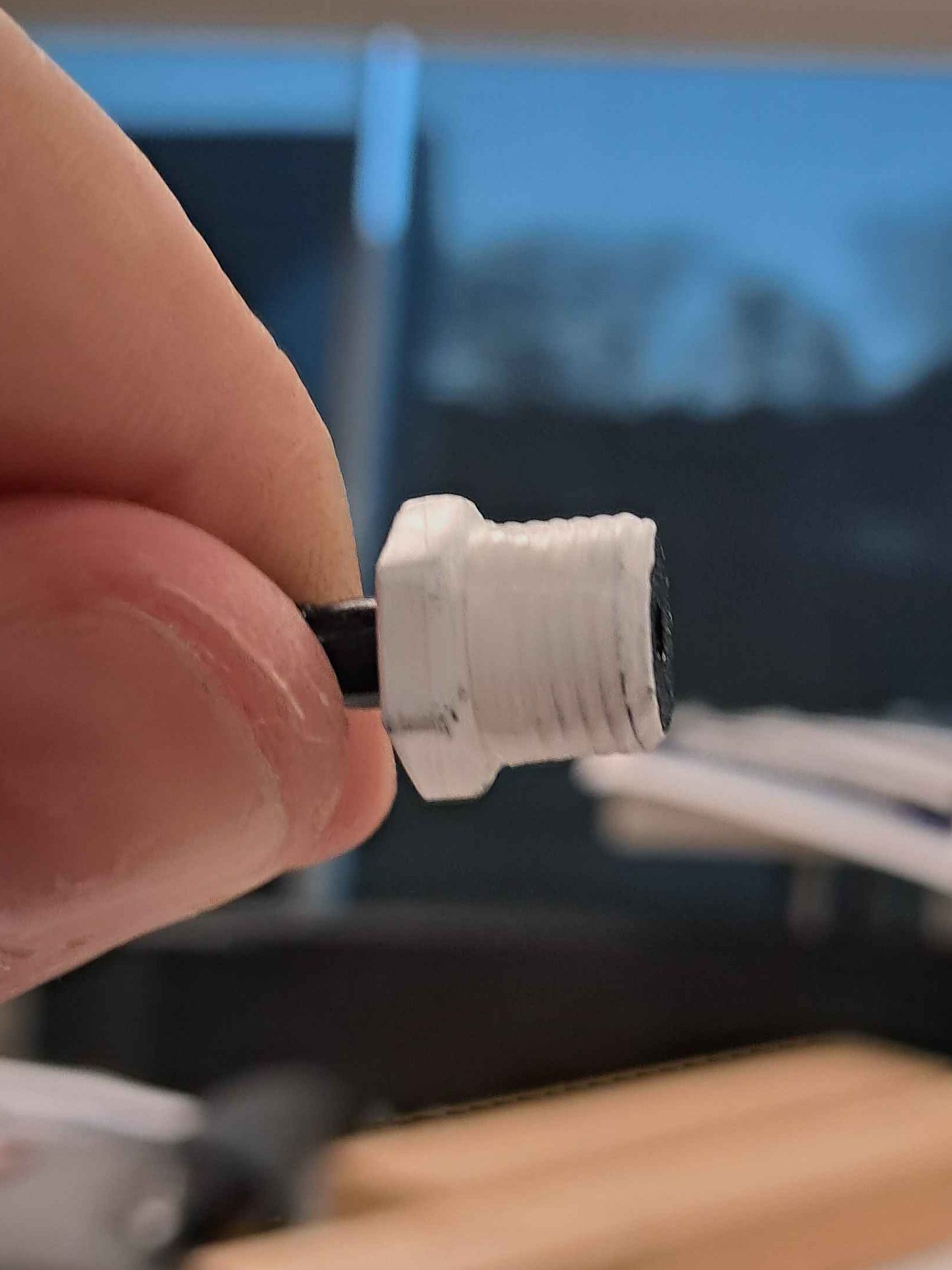
My first priority was getting the valve attachment ready, as this was necessary to be able to test the valves. This was both to make sure that it works, and to enable the software engineers to develop and test their valve control system. I started on this last week, with printing a threaded piece that matched the threads of the valve. Still, I needed to print with a hose barb on top to be able to attach our tube. From the test of the hydraulic cylinder, I knew I wanted the diameter of the hose barb to be larger, since it seemed to be leaking in the test. Since the previous hose barb easily snapped when printed right side up, I printed it laying on its side for optimal print orientation. I was worried that printing the valve attachment on its side would mess up the threads, so I decided to print it right side up. To my surprise, the increase in diameter of the hose barb led to it being much stronger, and I actually had difficulties snapping it.
With the valve attachment done, we were ready to test the valve. The video of this is shown below. The valve was successful in directing the water, meaning that the system was working. This is really great news! Granted, this test was isolated to the valve, and did not include any cylinder or manifold, but the component test was a success. There was as expected a lot of leakage from the valve attachments during the test. This is important to fix, as the problem would grow exponentially when connecting three more valves, and the remaining cylinders and manifolds.
From the test, it seemed like water was leaking both through the hose barb and the threads. The hose barb is not that surprising, since we used large zip-ties (because it was what we had easy access to). By using smaller zip ties, we should get a tighter seal, and the leakage should be fixed. For the threads, I was recommended using thread seal tape. I was sceptical at first, since the threads I was working with were so small, but decided to give it a go. Both the small zip-ties and the thread seal tape were easily obtainable at Clas Ohlson.
When we did the test again with these leakage reducing efforts, the system worked perfectly! There was no leakage at all during normal use. There was only leakage when the valve was blocking both paths, and pressure was building inside the valve, but this should not be a problem.
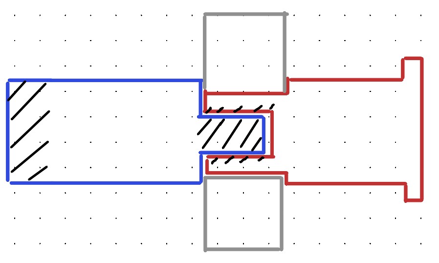
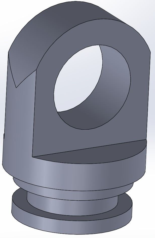
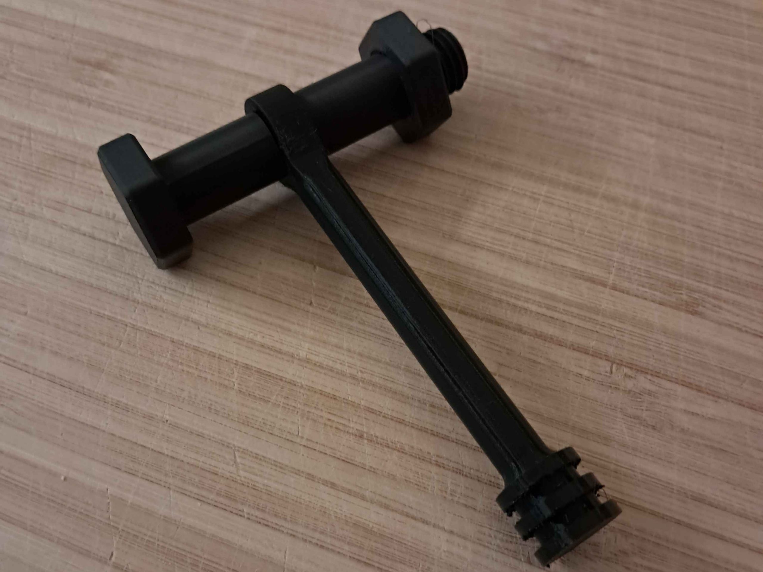
Now that the valve attachments do not leak under operations, it’s time to look at how the cylinder should be mounted to the arm. This will be the interface between the arm structure and the hydraulic system. The cylinder mounting positions were defined last week, check out our previous blog post for that. I wanted the cylinders to be easily removed from the system, seeing as they are vital components that we might want to swap out or work on free from the arm. With that in mind, I used threads as the fastening method, and designed an attachment rod with three components.
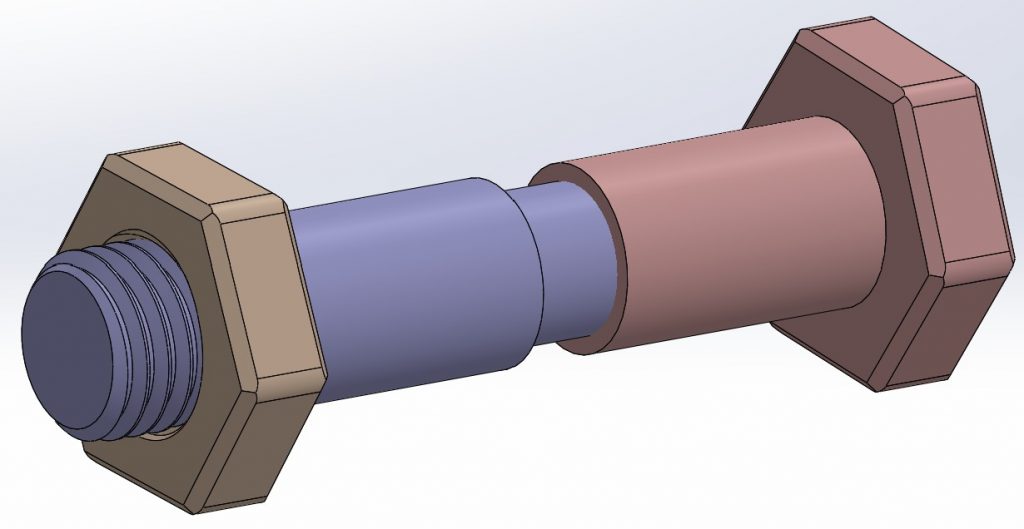
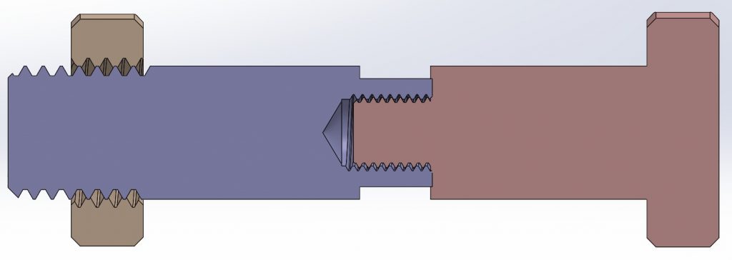
The cylinder attachment rod seemed to work fine, and was easy to implement to the arm. I also tweaked on the design of the hydraulic cylinder to match the attachment rods, meaning I added hoops to both the piston and the end cap of the cylinder. I made sure to have a small clearing in the prints, to make sure it was a good fit. When putting it all together, the fit was tight enough to hold it firmly in place, but not so tight that it limited the movement.
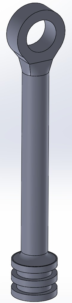
For the full hydraulic system, we need at least six of these attachment rods, as well as four cylinders. So printing components and putting them together will be much of my work the coming week. But hopefully we will have a fully working hydraulic system by the end of it.
Lisa:
This week, I had the chance to test the valve control system integrated with the pump, and the results were really promising!
After several weeks of software development, where I previously implemented the angle calibration for the potentiometer, I was now able to integrate it into the complete control structure. The potentiometer data is continuously converted into an angular value used by the control logic to determine the current state of the valves and the pump.
Seeing that data now directly controls real hardware felt like a big step; the software is no longer just code, but an active part of the physical system!
How the system works
The code I worked on this week was based on a structure that Syver had previously set up. I built upon this useful groundwork by refining the logic for activation, pump control, and timing to make it precise and stable.
The software running on the Arduino now acts as a small real-time control system that manages both the valves and the pump based on the angle measured by the potentiometer.
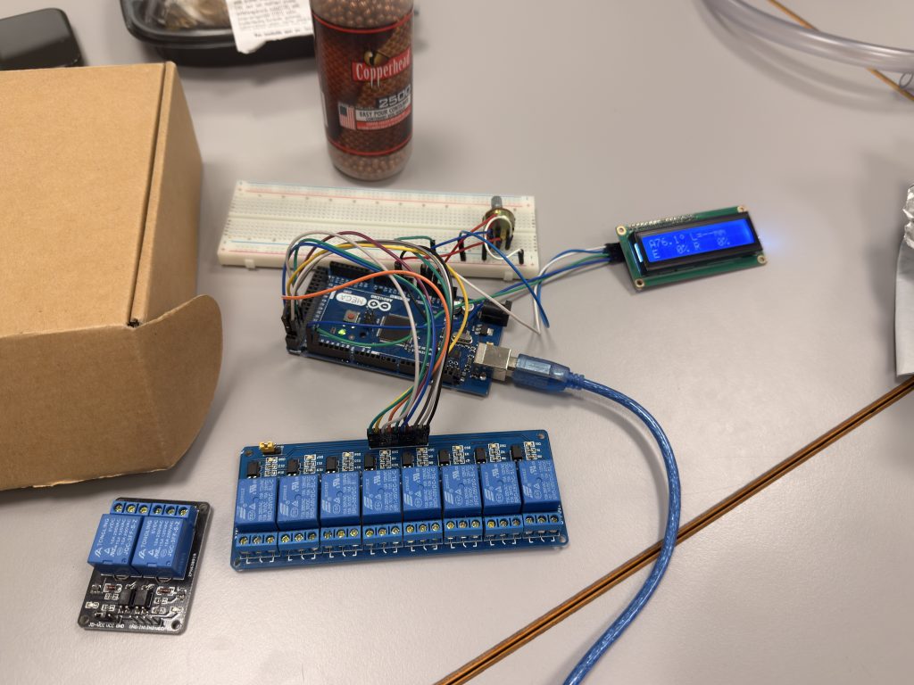
Each valve consists of two relay channels: one for Extend (E) and one for Retract (R). The code continuously reads the angle and determines which valve should be active:
- When the angle is below 76.1°, Valve 1 is active.
- When the angle is above 76.1°, Valve 2 takes control.
- And right in the middle, there’s a dead zone where both valves stay off to keep the system stable.
To prevent the relays from switching too quickly, I implemented time-gating, which enforces a minimum ON and OFF time for each channel. The pump logic was also refined. Instead of reacting directly to the relay outputs, it now responds to the intention of motion, meaning that the pump stays on while the system is in motion and turns off once the arm stops moving.
For example, if the arm moves from 54° to 74°, the pump initially remains off. As soon as the potentiometer begins to rotate and the arm starts moving toward its destination angle, the pump turns on and remains active throughout the movement. Once the arm reaches 74° and the motion stops, the pump automatically turns off again.
Of course, this isn’t a completely realistic situation yet, since the movement is currently controlled manually by rotating the potentiometer. While this manual control with the potentiometer was perfect for testing, the final version of the system will receive automatic movement instructions, for instance, from the image processing module. Using the same control logic, it will then know exactly where to move and adjust the valves accordingly.
Testing
For the test, we connected one complete valve with the pump to verify the behavior. The results were overall good, the valve correctly switched between extend and retract, and the pump followed the movement as intended.
However, during the test, we observed that the system was quite sensitive to changes in the potentiometer signal, especially from the software side. It required a steady and constant rotation to keep the system active, and even small variations in movement caused the control logic to interpret it as “no motion,” which immediately turned off the pump. This sensitivity made the pump logic a bit unstable at times, and it’s something I’ll need to fine-tune to make the system respond more consistently and reliably.
To sum it up, here’s a short clip from the test, where it is showing how the valve and the pump work together in practice:
Even though the system worked well during testing, there’s still room for improvement. I’ll be taking a closer look at how each valve’s state behaves under different conditions, to make transitions smoother and even more consistent.
Syver:
Last week, I wrote that I completed the control system for each joint, allowing the simulation to manipulate each angle based on keypresses. What remained was to implement the inverse kinematics, so the arm could operate on coordinates rather than target angles. I’ve also helped implement the base class structure for the Arduino controlling the kinematics.
Starting the week by working on the Arduino kinematics, I began by laying out the classes needed for the different components;
- LowFreqPWM: Copied from the Unity simulation, handles toggling outputs in correlation to the duty cycles (limited to 0, 20-80, 100%).
- Valve: Holds two LowFreqPWM instances, one for each end of the solenoid/outflow direction.
- Joint: Holds everything related to the joint; Valve class instance, potmeter pin, etc.
I then defined the different joint instances with pinouts, put them into a list, and made the Arduino loop() iterate over their update() methods. With the structure in place, I handed off the implementation to Lisa, who continued building out the logic.
Most of my week went into implementing the inverse kinematics in Unity, which will be transferred to the Arduino when done. I first researched what formulas were needed to resolve the angles for a two-segment arm, leaving the wrist segment till the end as it can be calculated using the resolved angles. Seeing as I’ve never worked with inverse kinematics before, I had to find some sources to learn from. Luckily, I found some very useful learning material online, which helped me understand the topic.
The arms given in the examples were similar enough that I could extrapolate much of the maths from there as well. The maths ended up being easier than I first anticipated, much thanks to our limited degrees of freedom. We only have 4, with 2 relevant degrees in the vertical plane. These are some excerpts from the maths:
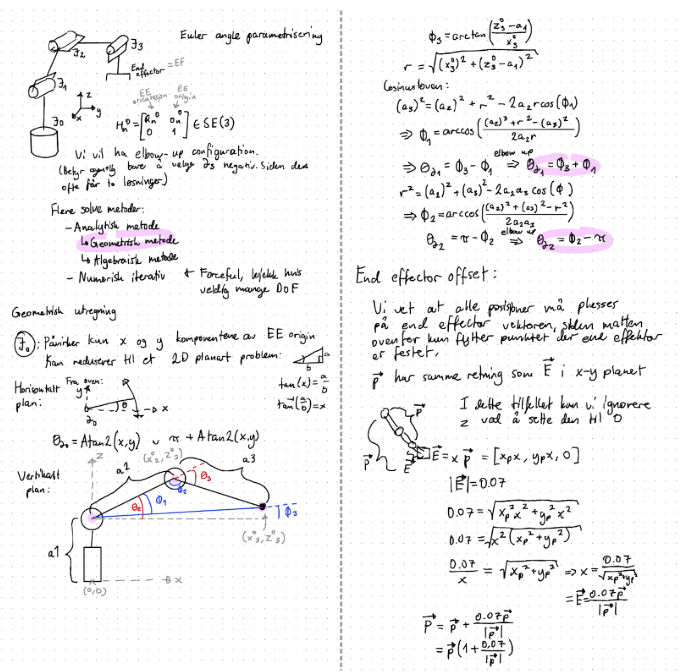
Summarized, the maths is divided into solving each plane. By first looking at the horizontal plane, we see that joint 0 is the only one affecting what orientation the vertical plane will be in. Using this fact, a simple Atan2 function is used to find its rotation around Z. The vertical plane was a bit trickier, and required some algebra and the law of cosines to compute.
I was on my own when calculating the end effector (or “wrist”) offset, which I solved by representing the end of the second segment as a unit vector, and multiplying with the length of the end effector segment (0.07m).
Implementing this in C# was straightforward after I had the maths laid out. After implementing this, the arm could handle movement in the form of coordinates;
I’ve also been helping with testing the solenoid valves together with the pump, as can be seen in Fredrik’s part.
Looking forward, some further tweaking needs to be done. This includes translating 2D coordinates from the drawing G-Code to a 16:9 aspect ratio rectangle enclosed within the circular band of reachability that the robot has around it. When that is done, I will shift my focus onto cooperating with the rest of the team in integrating all the different components into one big beautiful robotic arm.
Emory:
This week, I started looking into incorporating all the algorithms I have created for image processing into the website so that they can be displayed and utilised further. In the begining trying to import the image directly into main to use for the image shown in the UI did not work. The problem was by doing this the img.copy would clash with another img.copy from another code,
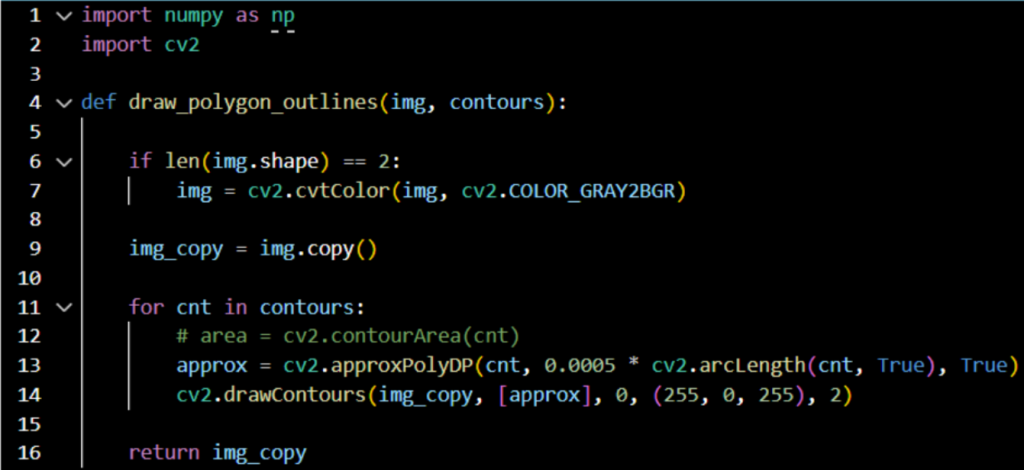
So by just importing functions that use it makes it so it’s possible to use the image created in the other files.So I had to start by fixing polygonOutline.py and ContourDetection.py to be a function so it can be properly used inside of main to show the sent image and have the contours on top of it.
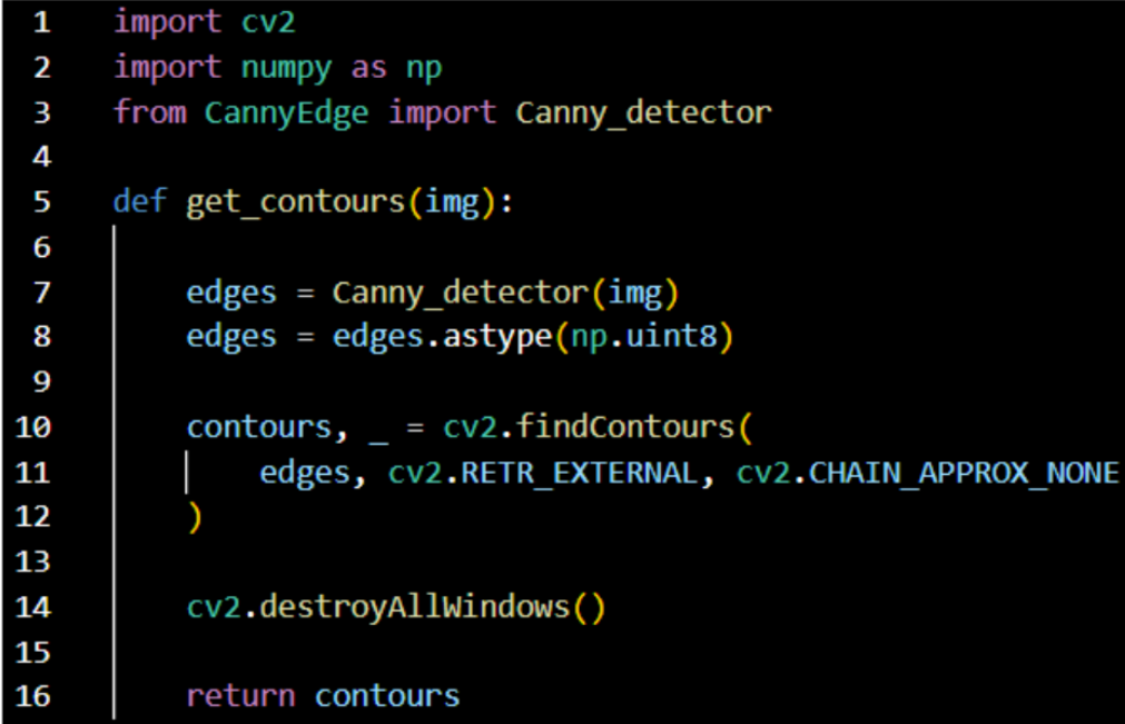
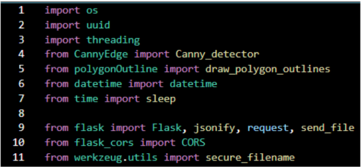
Started by importing the functions from the files I fixed.
Then added inside the apply_edge_detection to add the contour for the image so you can see what will be drawn.

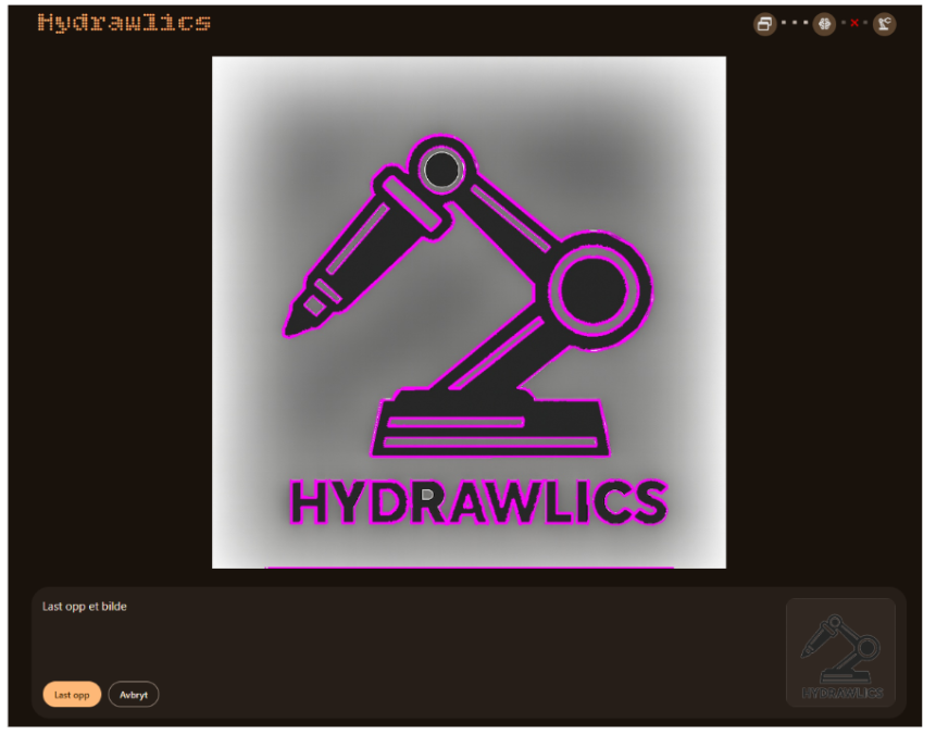
Showing the results from the website with our logo and the image I’ve mostly used so far. So below is how the website looks so far. This given a good view of the image you sent and what will be drawn shown in pink.
After fixing this, I looked at continuing the arduino_interface so the line algorithm can be sent over. I added the function find_gcode_file to the code to find the file being created and if name == “main” to sent the gcode from that file to the arduino.
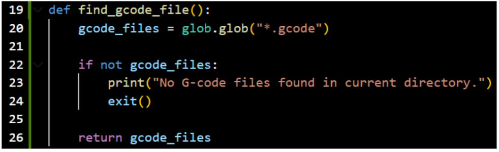
This function looks through the directory it’s inn to find a file that ends with .gcode. Which for use here it would find the output.gcode file which contains the gcode for the image that has been processed.

The other part of the code is to transfer the gcode to the arduino with a delay to avoid overwhelming the arduino serial buffer.
Didn’t get to test this yet, but is a good setup to use to try to run the code when we test the connection between the raspberry pi and arduino. So for the future it would be to further see the setup with the raspberry pi and the arduino together with the UI to see how it all works together.
This week have taught me global variables will make clashing between different codes more likely to happen, so putting them into functions makes life a lot easier.
Erling:
This week i have focused mainly on the input and exhaust manifolds for our hydraulic system, and making sure that we have a full understanding of what goes into our hydraulic system. And i have done some simple design alterations and assembly of the radaxial bearings in the arm base unit.
In our hydraulic system, we have the following components:
- valves x4
- cylinder x4
- printed push-to-connect fittings x20
- manifolds (Distribution and collector)
- pump
- tubes (10mm and 4mm)
- reservoir
- printed barb fittings (2x 10mm and 12x 4mm)
Fredrik has made the design for the cylinders, and we have purchased valves and the pump as previously described. The reservoir can be made as easy as a bucket full of water, and the tubes are purchased from Tools in Kongsberg.
The manifolds have been designed and are ready for production, which will happen in the coming week.
There are two distinct variants of the manifold as shown under:
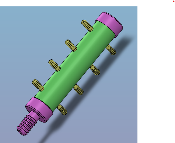
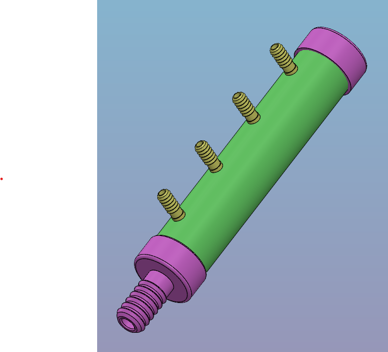
Collector manifold on the left. Distribution manifold on the right.
The distribution manifold has 4 outputs (barb fittings), each to the Pressure port of its respective valve. The collector manifold has 8 inputs (barb fittings) to collect from the exhaust ports from the valves, and consolidate the flows to the reservoir.
I will print the caps and the barb ends (pink) on a 3d printer and glue them with 2 part epoxy to the manifold tubes that have holes in them. This should create a watertight seal and function as designed.
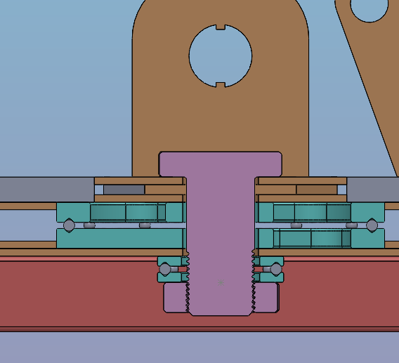
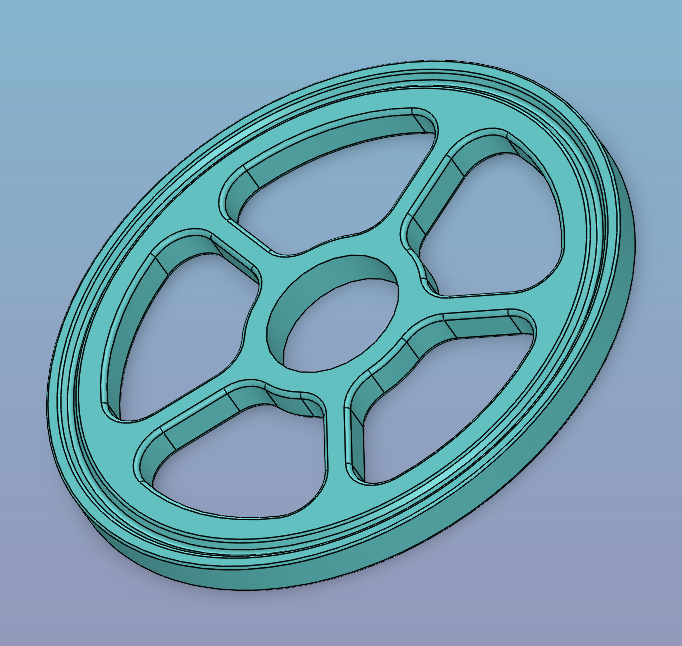
I realized that i made small mistake in the previous design for the radaxial bearings for the arm base, so i redesigned the large one to better suit the needs of the project.
I added the rolling elements of the bearings to the main assembly, so now the arm base moves as it is intended to. I discovered that the resistance in the radaxial bearing is adjustable with center bolt pretension as the rolling elements are made of steel, and the bearing races are PLA, it is possible we get some creep due to viscoelastic effects over time. this wont be an issue for our use case as we can progressively tighten the center bolt or easily print new and replace deformed parts.
In all, we have conducted the tests we wanted to at this stage, and gotten a better hold of the physical form of the hydraulic system as a whole. We have tested each component individually, and can say with a degree of certainty that our approach will work when implemented.
That’s all for now, see you next week!