Theo:
This week, I managed to get the servo working. I did some troubleshooting with a multimeter and found that the issue was insufficient power to the servo. After connecting the servo to the driver board and powering it with a power bank, it started working. Once the arm is ready, I’ll calibrate the servo and it will be able to move the box.
Sondre:
This week involved quite a bit of troubleshooting and debugging on my part. We finally received the BNO055 IMU module last week, and over the weekend Anette was able to solder the pin headers so it could be mounted on the robot’s expansion board. My main goal this week was to get the IMU communicating reliably with the Micro:bit and integrate it into the robot’s control system.
Me and Anette connected the BNO055 to the Micro:bit Driver Expansion Board using the built-in I2C connector. The table below shows the pin mapping I used for this connection:
| BNO055 (IMU) | Micro:bit expansion board: |
| Vin | 3v3 |
| GND | GND |
| SDA | SDA |
| SCL | SCL |
| PS0 | GND |
| PS1 | GND |
| ADR | 3v3 |
And the I2C connection on the driver expansion board is shown below.
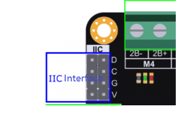
When we first connected the IMU, it did not appear on the I²C bus. I expected to find it at address 0x28 or 0x29, depending on whether the ADR pin was set low (GND) or high (3V3). To verify the connection, I used an I2C scanner script that I generated with help from ChatGPT. When I ran the scan, only the motor driver’s addresses appeared, meaning that the IMU was not responding at all.
At this point, I suspected a hardware issue so I checked the power connections with Anette and Robin to confirm that the IMU was receiving voltage. Everything looked fine, which ruled out a power problem. Eventually I decided to swap the SDA and SCL lines, and that turned out to be the issue. After switching the connections, the IMU was successfully detected at address 0x29, confirming proper communication over I2C.
To interface with the sensor, I installed the Adafruit BNO055 library via PlatformIO. This made the integration straightforward, as the library handles sensor initialization.
I then uploaded a simple test program to confirm that the IMU was sending orientation data:
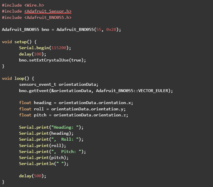
Now I could see in the serial monitor that I got all the readings from the IMU:
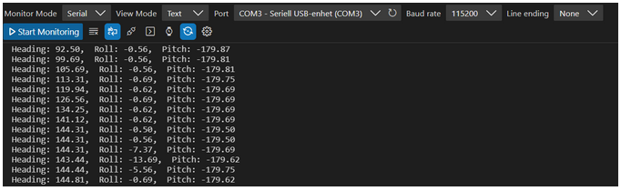
But the only one I was interested in was the heading. So next was to try to implement this in the code for the robot.
The idea I had with buying the IMU was that with an absolute heading reading I could use that to make it drive straight in the path. I also wanted it for turning since now it would no longer depend on turning for a set time but rather turning based on degrees.
Now that I had gotten readings from the IMU, I could start integrating it with the robot’s navigation system. I reused the turning functions I developed last week, but instead of relying on the ultrasonic sensors to trigger course corrections, the robot now uses the IMU’s heading data to detect and correct angular drift.
To achieve this, I calculate the difference between the robot’s current heading and its target heading using a simple formula that keeps the value within the range of –180 degrees to +180 degrees. This difference, called diff, tells the robot whether it has rotated slightly left or right from its intended direction. By using symmetric thresholds, I can decide which rotation function to call:
- If diff is greater than +20 degrees, the robot has turned too far to the right, so it performs a small left rotation to correct its course.
- If diff is less than –20 degrees, the robot has drifted to the left, and it performs a right rotation.
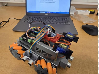
Over you can see how I temporarily mounted the IMU with the use of a breadboard.
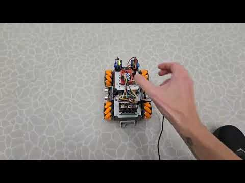
Here you can see how it rotates a bit when it is of course. It does not rotate much since the function only runs for 100 ms. But it shows proof of concept.
Next week, I’ll focus on improving how the IMU works with the robot.
While testing the robot, I noticed that it doesn’t always drive perfectly straight, each new test session tends to drift slightly to the left or right. This shows that relying only on the IMU and calibration values isn’t always reliable, since small mechanical differences or battery levels can affect the motors. Adding encoders to the motors would make it possible to measure the exact wheel rotations, allowing for better control and more consistent movement. During the guest lecture, we learned how reliability is critical in systems that operate in space, where even small errors can have big consequences. I think this idea connects well to our project. Making the robot’s movement more predictable and reliable is just as important here, even if it’s on a smaller scale.
Anette:
This week I was going to test the PCA9685 board with a SG90 servo motor. This is the same one we are going to use for the arm attachment. The board didn’t include a capacitor, so I had to figure out which one to use and where to acquire it. I asked around to see if I could get it from someone I know, but ended up asking Henning on friday. I was then unavailable during the weekend so I’m not able to test it until monday. I did test the soldering from last week to see if I had to fix anything, and it worked. I also want to test the motors on the car itself, but I have to find my equipment at home, and there is still some uncertainty about which motors we are going to use. We also have 2 weeks left to order and finish the pcb, so we have to start looking into the process of ordering it.
Matias:
This week I made significant progress in the design phase of our project. Both the motor controller and the voltage regulator for its power supply are now fully completed in Capture. It has been satisfying to see all the components properly placed and connected in the schematic, and it gives a clear overview of how the system will function once assembled.
Next, I will move on to PCB Editor to start laying out the physical board. This step will allow me to translate the schematic into a real, manufacturable PCB, taking into account component placement, trace routing, and overall design efficiency. I am looking forward to tackling this part because it is where the design really starts to take shape in a tangible way.
Below are screenshots of the completed schematics in Capture:
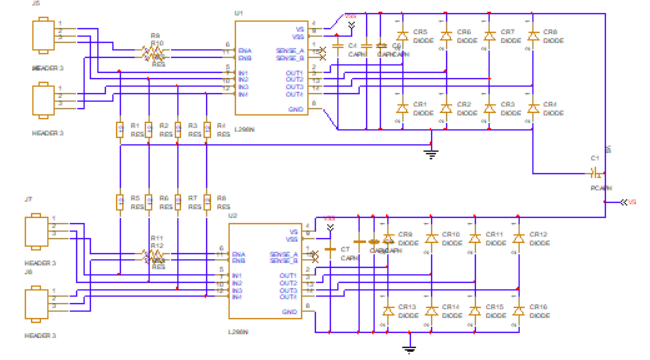
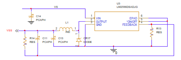
Completing these schematics has helped me better understand the interactions between components and the practical considerations for power delivery and motor control. I’m excited to start the PCB layout next and see how all the pieces come together.
Robin
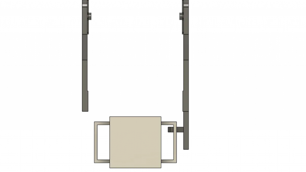
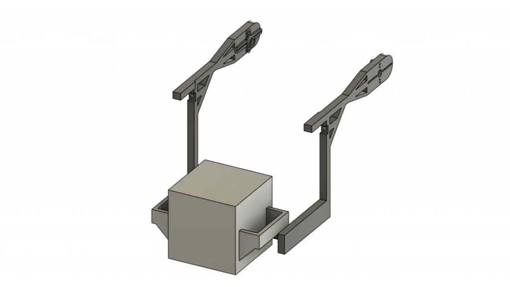
Evolution of the Gripping System Design
The work for Week 8 focused on redesigning the robot’s front arm and the package handling system.
The initial concept, which involved a lifting arm module sliding under the object, was abandoned in favor of a more direct approach. We designed a custom box equipped with specific handles that the robot’s arm grasps to perform the lift.