Wang
Micro:bit v2 pairing/connection
Now I have received a new task, I will look at communication between micro:bits via Bluetooth.
Why look at this? It’s because the car should mainly drive by itself using sensor data. But it’s not 100% reliable. So it’s smart to have a way to control the car manually if it turns out that it gets stuck and can’t get loose because maybe an obstacle wasn’t detected or something like that. It’s also useful because since the theme is somewhat moon mapping/mars, it can be nice to control the car a bit yourself if you discover exciting places, you can manually drive the car there.
So the plan to complete this.
So first now I’ll do some searching and research on how this should be done and how I should start with this task.
Zephyr and the BBC Microbit V2 Tutorial Part 4: BLE – Zephyr Project
So what I’ve tried now is that I use ready-made examples from Zephyr to see if the two micro:bits can make contact. I use then.
samples/bluetooth/central_uart
samples/bluetooth/peripheral_uart
Both are up and running which is a good sign that Zephyr works, but they don’t find each other.
Output from serial
*** Booting My Application v3.1.1-f02b5daf0cee ***
*** Using nRF Connect SDK v3.1.1-e2a97fe2578a ***
*** Using Zephyr OS v4.1.99-ff8f0c579eeb ***
Starting Nordic UART service sample
*** Booting nRF Connect SDK v3.1.1-e2a97fe2578a ***
*** Using Zephyr OS v4.1.99-ff8f0c579eeb ***
Starting Bluetooth Central UART sample
My suspicion and reason why this didn’t work is because this is an example from NORDIC and on their pages it states the following boards that this code supports and micro:bit v2 is not mentioned there.
But I will look at more of the examples they have on Nordic’s pages and see if I find something that can help me.
Choice
- [x] Bluetooth
- [ ] Radio
I have chosen to use Bluetooth because it’s easier to start with on Zephyr since there are already several ready-made examples that I can use and take advantage of. They should both be quite similar in range and I’ve heard from other students that radio is actually easier to use than Bluetooth, but there isn’t as much of it on Zephyr as there is on makeCode and since I won’t be using that, it became Bluetooth.
For this project, the range isn’t the most important since we will be more simulating how it should behave now. But if it actually were to be sent up to say the moon, then radio and Bluetooth signals would be far too weak and would most likely use some LORA technology to communicate.
Links/pages I’m looking at
sdk-zephyr/samples/boards/bbc/microbit/pong at main · nrfconnect/sdk-zephyr
PONG
Here I got an example from Zephyr to work between two micro:bits over Bluetooth. So now that we know the micro:bits can talk together with Zephyr, we can use this code as a starting point for what I have set as a goal for this project.
When I was setting this up, I had to go to Create a new application, then Copy a sample, then search for pong. Then add build configuration, build for the micro:bit, then open the terminal and enter this.
west build -b bbc_microbit_v2 -d build_client -- -DCLIENT=1
it then builds a build_client so in the pong folder you should have 2 folders, one build and one build_client
And finally you flash. You can only flash 1 micro:bit at a time, so when you take one, the other must be unplugged.
for the build folder
west flash -d build --erase
for the build_client folder
west flash -d build_client --erase
now everything should be ready. Then you can press both micro:bits’ reset button, then hold both front buttons simultaneously and you will get a message on the serial monitor
Started scanning for devices
and then it should only take a few seconds before you get this
Found matching device, initiating connection… Connected
Henning
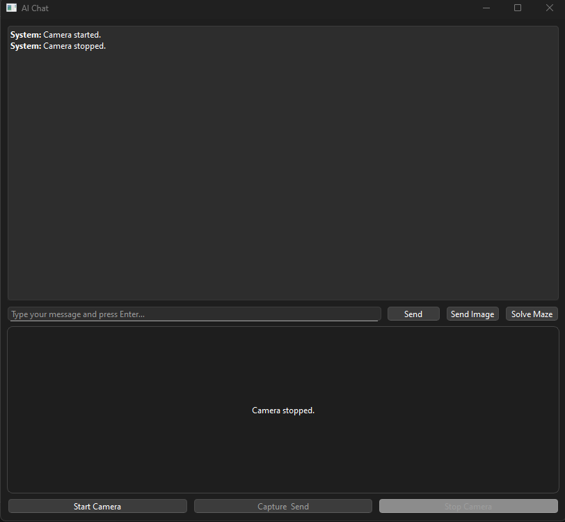
This week i managed to evolve the AI communicator even more. So at the moment of time the UI for the AI is like the image below shows. I have now added a “Solve Maze”, “Start Camera” and “Capture Send” button. The solve maze button is not fully finished, and still under development.
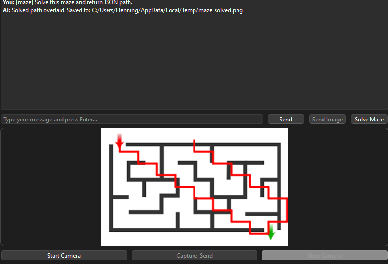
The solve maze button is basically the “send image” button, but specifically made for mazes. So if i send in a picture, the AI sends back a new image where it draws a path through the maze. As clearly seen here, i have some wrongs in the code, but as mentioned earlier, it is still under development.
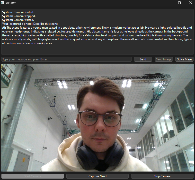
Now this video below illustrates how the “Start Camera” button functions. It connects to a live feed camera. I have yet to test if i can connect a different camera through USB and use that. But i can capture pictures from the live feed in which the AI will respond to the picture being sent in (look last image)
As mentioned in the text above, here i captured a photo of myself through the live feed camera. The AI Describes the picture as a whole.
Further for next week:
1. I will try an fix the painter for the maze
2. Connect a different camera through USB in order to access it with the AI
3. I will check the possibilities for setting up a memory for the AI as it now has no memory and resets after each use.
PS: Also want to give a huge thanks to out teacher Steven for all the help he has provided through some of the walls i have met in this project!
Zardasht
My goal is to create a system where the Raspberry Pi can detect and recognize object shapes using its camera, and then send that data to a control platform—either a web server or another system for further processing.
Together with Øyvind, we’re joining forces on a Raspberry Pi project that blends our individual ideas into a shared vision. By combining our strengths and perspectives, we’re aiming to build a solution that’s both creative and technically robust.
Øivind
“What if the best of the best ideas from every project in Smart Systems-25 was merged?”
Monday 13/10 yeah!
Fruitful (at least for me) meeting with Steven with the whole group. My shoulders are both relaxed and tense, mostly relaxed,more focused and the crosshair barely wobbles around the target. After a less successful tryout with two different DC-DC Buck/Step-Down converters, my thought was that size matters, but that Steven’s Buck I mentioned in the last blogpost at least measured correct value. I’m happy to have green light to focus a little “mechatronic” on our car. Though I read between the lines the end-result is what matters. Still a sunshine through the mist.
Video showing me failing while trying out two different DC-DC converters. Got help from Zardhast in my group to be my two extra arms. The problem was resolved later that day. Also some seconds of my first LEGO/cardboard glued mock up.
https://vimeo.com/1128788017?share=copy&fl=sv&fe=ci
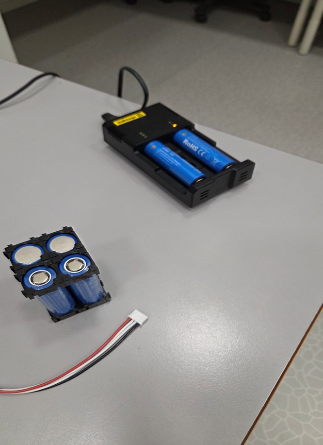
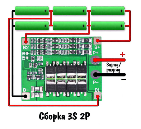
I have got hold of a spot welder to spot-weld the battery-pack, assembled in a 3S2P manner. 6 NEXTAR Li-Ion INR 18650 3.6V, 2600mA, 9.36Wh. These are what I got recommended in class, and they are now to get spot-welded together with a nickel band and I will attach a BMS to appropriate balance leads. This pack will serve as the power-supply for the whole car from now on.
Charging the batteries to full potential before welding
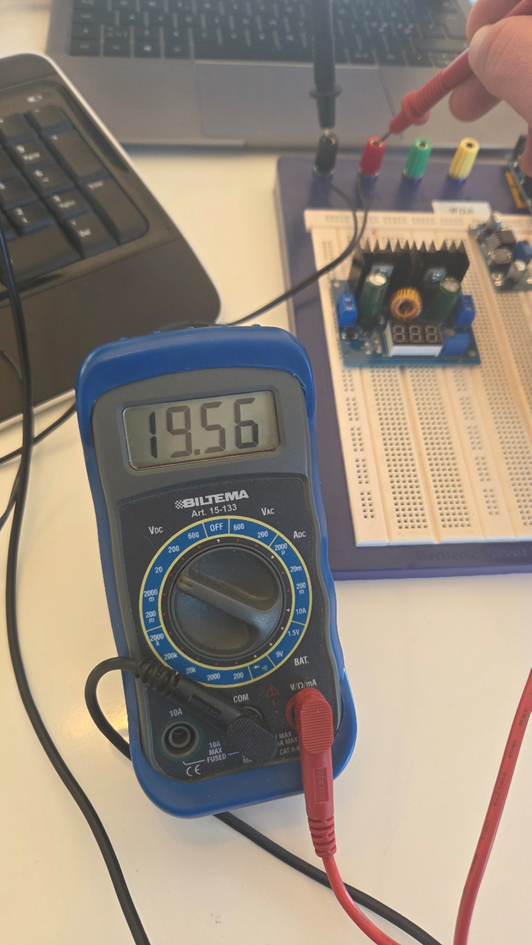
Verification of output voltage from power supply, which I will step down to 12,6 Volts through a XL4016 DC-DC Step down converter. This will be my portable charger for the battery pack. Power to the Buck will be delivered through a small, switched power supply.
Before I spot-weld the battery pack, I test the equipment on an older battery-cell. I have ensured that the battery stands stable and I use a fireproof cloth and safety glasses in case of an accident.
The first two sparks startled me, which I guess looks funny to the viewer. You are allowed to laugh 😊
Now that I see the spot-welder works as intended, I can finally weld my battery-pack.
After I’m finished the 3s2p battery pack, I will attach a BMS as shown below.
The video is quite long. It’s several clips merged. Feel free to adjust the speed to 2x and skip through parts of it. Enjoy! https://youtu.be/zw_GAJvGg60
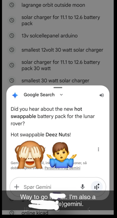
Googled: lunar Gateway space station, and shortly after asked for hot swapable solutions for industrial machines. And very often I google in Chrome, that Gemini entity shows up on top. Last night it had the nerve to be quite rude…
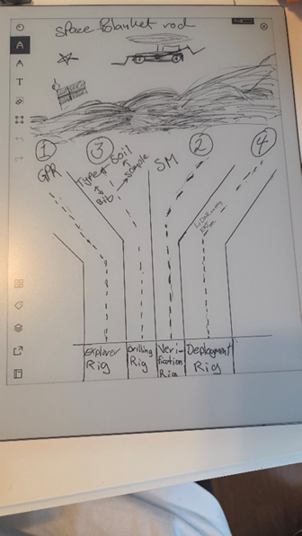
Quick sketches to copy before editing by hand
Sunday was the day to research the moon surface. Seems lunar Regolith is something that will affect every part of the project regarding the rover and it’s systems. The drilling process will be quite different on the lunar surface than here on earth. This information is available and some research and acts towards solutions you can find on nasa.org
One idea I find particularly interesting is Electrodynamic Dust Shield (EDS)
For tomorrow my plan is to further iterate on the mechanical arms, and options for sensors. Many of my drawings and ideas are in the bin since new implications steadily show up.
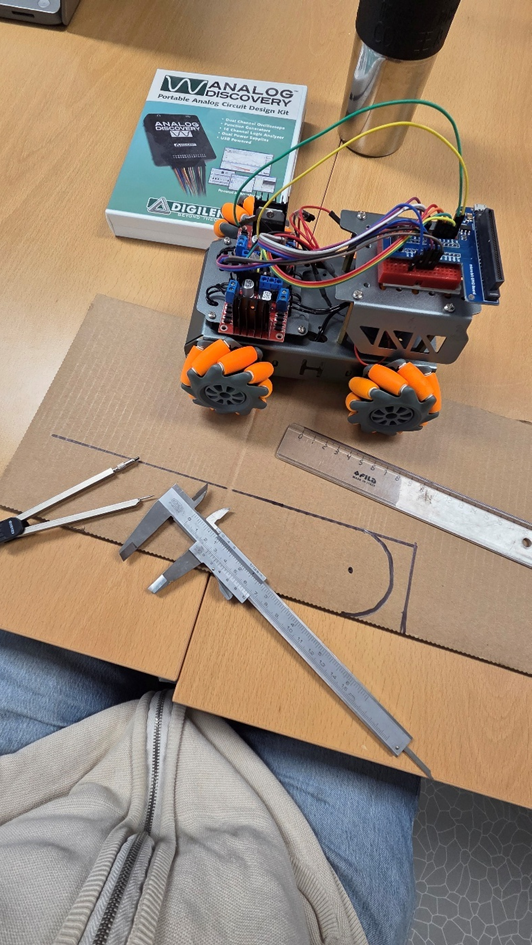
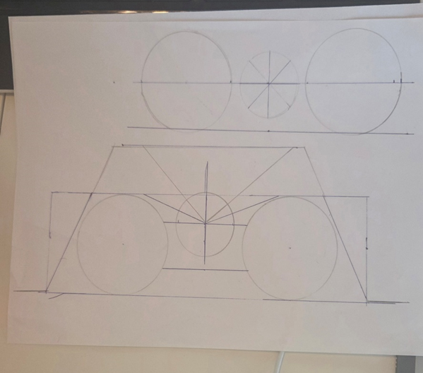
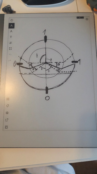
Today, Monday morning I warm up with last night ideas. Considered limitations for the mechanical structure. The pictures show some of the workflow. It’s easy to see that software is helpful when drawing.
Ideas: Left is first drawing considering mechanical arm limitations (binned)
Right is a drawing of base-station for the swarm of lunar rovers, which will have different tasks to fulfill. At the moment I hope ONE of the functions (rover base-station interaction) can be displayed and presented in the “exam”.
I think I will use Laser/ToF (Time of Flight) and/or analog IR sensors as distance measurement for obstacle avoidance.
Most recent plan for power supply is to implement both power bus and ground bus to avoid long daisy-chained wire-hauls. It will help when I shall connect everything later, and when troubleshooting when (it will happen) the shit hits the fan.
Mass and size is already an issue. So I will need to be considerate about planning for too much further. I already have in plan a motorized telescope-”antenna”, for multi-purpose use. Use-case can be camera, EM shield or anything that fits, when you need an elevated spot over the rover.
Oskaras
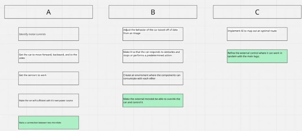
On monday we discussed our plans towards and decided on more distinct tasks for all the members to eliminate the dependency on progress from select members, and that everyone can progress with out bottlenecking. I got complete assignment for the control of the motors, while also being the one to visualize our progress with sprints and ABC setup.
abc setup:
sprint overview for last week: the overview isn’t ready for this week, but i will make it complete the next week with both for last week and this coming week.
On Friday i met with Steven and received some examples on zephyr code that were a huge help as a reference since older version code is scares and very limited. i also got a better idea how to troubleshoot while working with zephyr
troubleshoot:
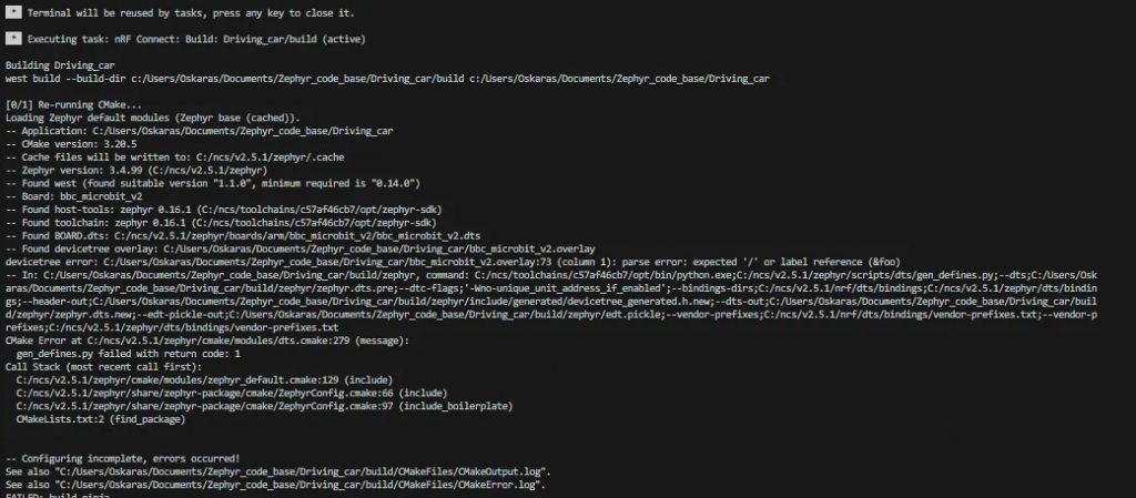
From c++ in visual studio, and python in spyder i was to used to having a red line tell me where the issue is, not necessary the solution but attest where it was located. In zephyr that wasn’t the case for the most part. It still detects if a variable isn’t initialized for example but not if say the overlay file has an error or misspelling. then it just throws out a message that brings you to a file with thousands of lines of code and leaves you there not explain anything. The actual error is told in the terminal when the initialization of the files happen and it is only there that the actual error is written out.
By using my newly acquired knowledge in error handling i’ve finished the pwm setup and “Compiled”
/ {
    zephyr,user{
        pin_19: pin_19 {
            gpios = <&gpio0 19 0>;
        };
    };
};

&pinctrl {
    spi1_default: spi1_default {
        group1 {
            psels = <NRF_PSEL(SPIM_MOSI, 0, 13)>,
                    <NRF_PSEL(SPIM_MISO, 0, 14)>,
                    <NRF_PSEL(SPIM_SCK,  0, 15)>;
        };
    };

    pwm0_default_alt: pwm0_default_alt {
        group1 {
            psels = <NRF_PSEL(PWM_OUT0, 0, 2)>;
            nordic,invert;
        };
    };
    pwm0_sleep_alt: pwm0_sleep_alt {
        group1 {
            psels = <NRF_PSEL(PWM_OUT0, 0, 2)>;
            low-power-enable;
        };
    };

    pwm1_default_alt: pwm1_default_alt {
        group1 {
            psels = <NRF_PSEL(PWM_OUT1, 0, 3)>;
            nordic,invert;
        };
    };

    pwm1_sleep_alt: pwm1_sleep_alt {
        group1 {
            psels = <NRF_PSEL(PWM_OUT1, 0, 3)>;
            low-power-enable;
        };
    };


};

&pwm0 {
    status = "okay";
    pinctrl-0 = <&pwm0_default_alt>;
    pinctrl-1 = <&pwm0_sleep_alt>;
    pinctrl-names = "default", "sleep";

    label = "PWM_0";
};
&pwm1 {
    status = "okay";
    pinctrl-0 = <&pwm1_default_alt>;
    pinctrl-1 = <&pwm1_sleep_alt>;
    pinctrl-names = "default", "sleep";

    label = "PWM_1";
};

leds {
    compatible = "gpio-leds";
    led14: led_14 {
        gpios = <&gpio14 14 GPIO_ACTIVE_LOW>;
        label = "LED 14";
    };
};
aliases {
    led0 = &led_14;
};
iv’e started to set up the gpios now using the leds on a normal breadboard to test the code and using the example help with nordic academy guides