Sondre:
This week I have not done anything huge but rather a couple smaller things that needed to be done. I have focused on testing smaller bits and pieces and getting them to work, since I am waiting on some parts I have ordered for the project.
I started by testing the cars movement and when I tested the car I saw that it did not go straight. And since we at this point don’t have motors with encoders or a gyroscope to sense the direction of the car, I decided to fix this in code. The way I did this was to add a calibration variable to the wheel setup. Since all the wheels are controlled by a function that sets all the wheel speeds for the different actions it was fairly easy to add a calibration variable.
const float cal_m1 = 1.00f;
const float cal_m2 = 1.00f;
const float cal_m3 = 1.00f;
const float cal_m4 = 0.90f;
static void setAll(const Motors &m, float scale = 0.8f) {
drv.motor_1(m.m1 * scale * cal_m1);
drv.motor_2(m.m2 * scale * cal_m2);
drv.motor_3(m.m3 * scale * cal_m3);
drv.motor_4(m.m4 * scale * cal_m4);
}
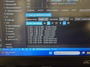
Here i have added a calibration variable to each wheel. And since the front right wheel was turning a little faster than the rest, I sloved it a bit down. Results before and after can be seen below:
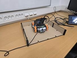
Next I started testing the robot in the environment we want it to move in. My goal was now to make it return the correct scenes. I wanted it to return scene::clear if the path was clear. And I wanted it to return the correct scene for when it is a box in the path or if it has encountered a wall. This was done by changing the tolerances to the size of the arena.
I have ordered a IMU so that the robot has a sense of how it is rotated in the path. But for now I have added a timer for how long it will rotate when it encounters a wall. This is not optimal but since it does not at this point have a clue how much it has rotated. This was the simplest solution for getting it working. But when the IMU is ready I am hoping it can control the rotation of the car in the path.
The last thing I have done this week was trying to get the car to move somewhat reliably trough a path. I change multiple parameters, like how close it should detect a turn. I got it to move through the course, but I also saw that it is not reliable since it strafed of course. And if we want to pick up a package it needs to stay centered. So to improve how the robot keeps itself centered in the path, I also started working on a centering function in the code. The idea was that if one of the side sensors detects that the robot is getting too close to one of the walls, it should move (strafe) slightly to the opposite side to re-center itself. For example, if the right distance sensor measures a value below a certain threshold, the robot strafes to the left, and vice versa. To make this correction more intelligent and avoid the robot constantly overcorrecting, I added a counter that keeps track of how many times it has had to strafe in the same direction. When this counter reaches three, the robot will slightly rotate in the opposite direction instead of just continuing to move sideways. This helps it correct its heading if it has been drifting diagonally along the wall. This centering logic made the robot move more smoothly and maintain a more stable position in the middle of the path, but it is not optimal and will need to be refined.
Her you can see it moving through a path before I added the correction code. I forgot to take a video of it after.
Overall, this week focused on fine-tuning basic movement and environment detection. While the robot can now navigate simple paths, consistent orientation and centering will depend on integrating the IMU and refining side sensor logic next week.
Théo :
I started looking into communication between two micro:bits as planned last week, but after some research, I couldn’t find any working code for it. The only possible way I found was using Python, but since we weren’t using that language, we decided to change our plan.
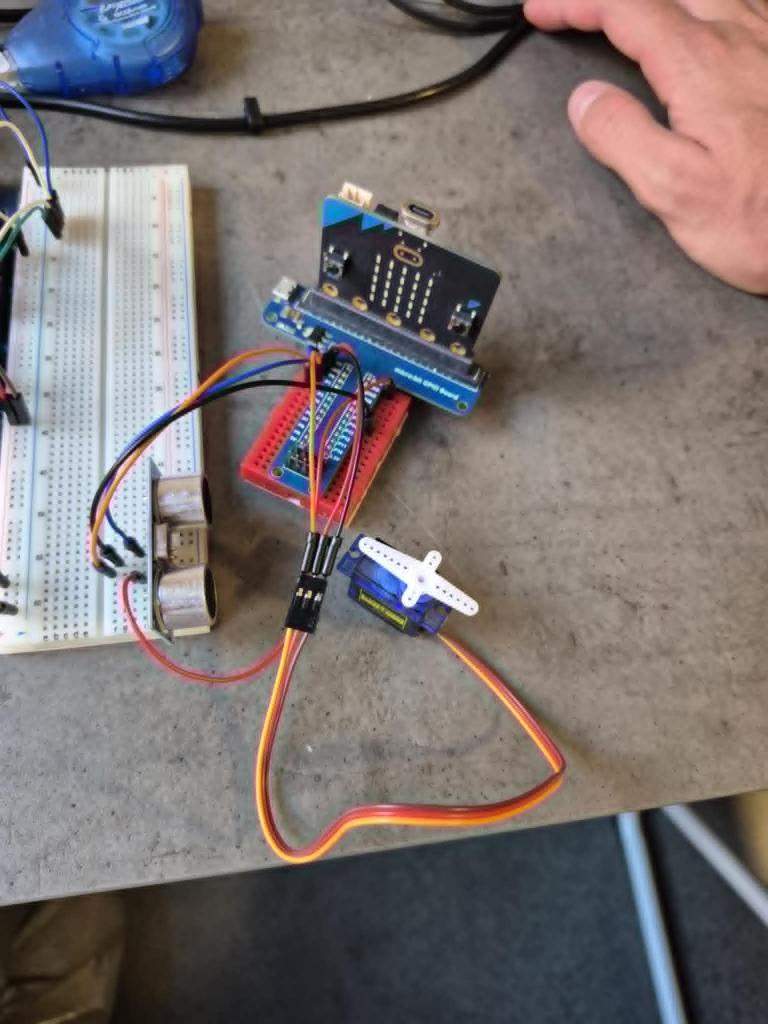
Then, I checked how to use the micro servo SG90. For now, I haven’t managed to make it move yet. I connected it to a sensor so that the servo would move depending on the distance.Here is the last version of the code I tried :
#include <Arduino.h>
#define SERVO_PIN 0
#define TRIG_PIN 1
#define ECHO_PIN 15
const float SOUND_SPEED = 0.0343;
const unsigned long TIMEOUT = 30000;
void setup() {
Serial.begin(115200);
pinMode(SERVO_PIN, OUTPUT);
pinMode(TRIG_PIN, OUTPUT);
pinMode(ECHO_PIN, INPUT);
digitalWrite(TRIG_PIN, LOW);
Serial.println(“Servo + capteur prêts !”);
}
void servoPulse(int pin, int angle) {
int pulseWidth = map(angle, 0, 180, 1000, 2000);
digitalWrite(pin, HIGH);
delayMicroseconds(pulseWidth);
digitalWrite(pin, LOW);
delayMicroseconds(20000 – pulseWidth);
}
float readDistance() {
digitalWrite(TRIG_PIN, LOW);
delayMicroseconds(2);
digitalWrite(TRIG_PIN, HIGH);
delayMicroseconds(10);
digitalWrite(TRIG_PIN, LOW);
unsigned long duration = pulseIn(ECHO_PIN, HIGH, TIMEOUT);
if (duration == 0) return -1;
return duration * SOUND_SPEED / 2.0;
}
void loop() {
float distance = readDistance();
if (distance < 0) {
Serial.println(“Pas d’écho”);
return;
}
Serial.print(“Distance : “);
Serial.print(distance, 1);
Serial.println(” cm”);
int angle;
if (distance < 15.0) {
angle = 90;
} else {
angle = 0;
}
for (int i = 0; i < 5; i++) {
servoPulse(SERVO_PIN, angle);
}
delay(250);
}
Anette:
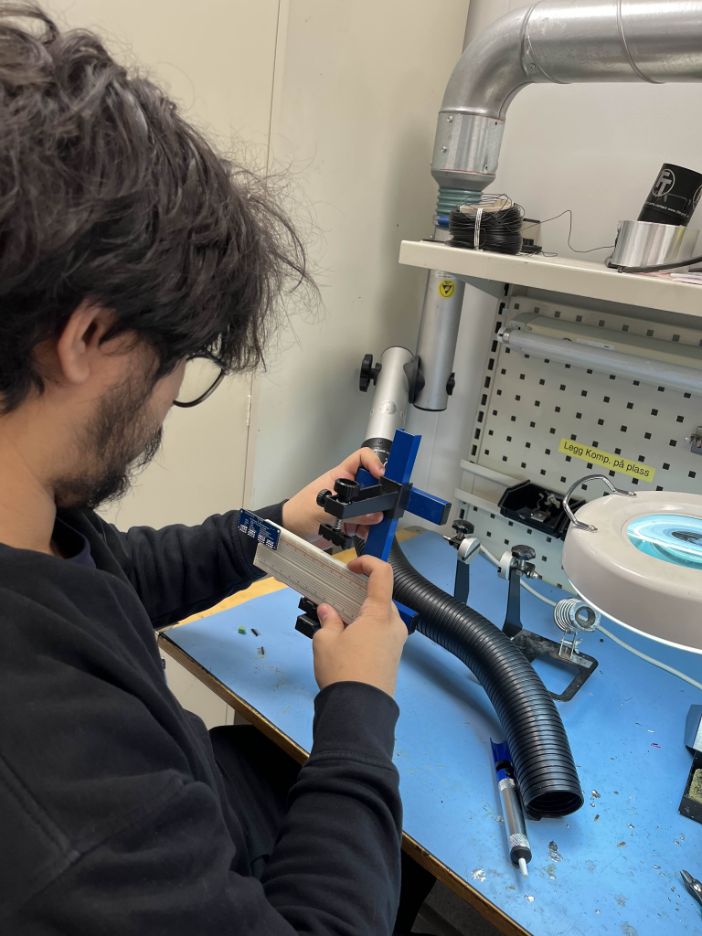
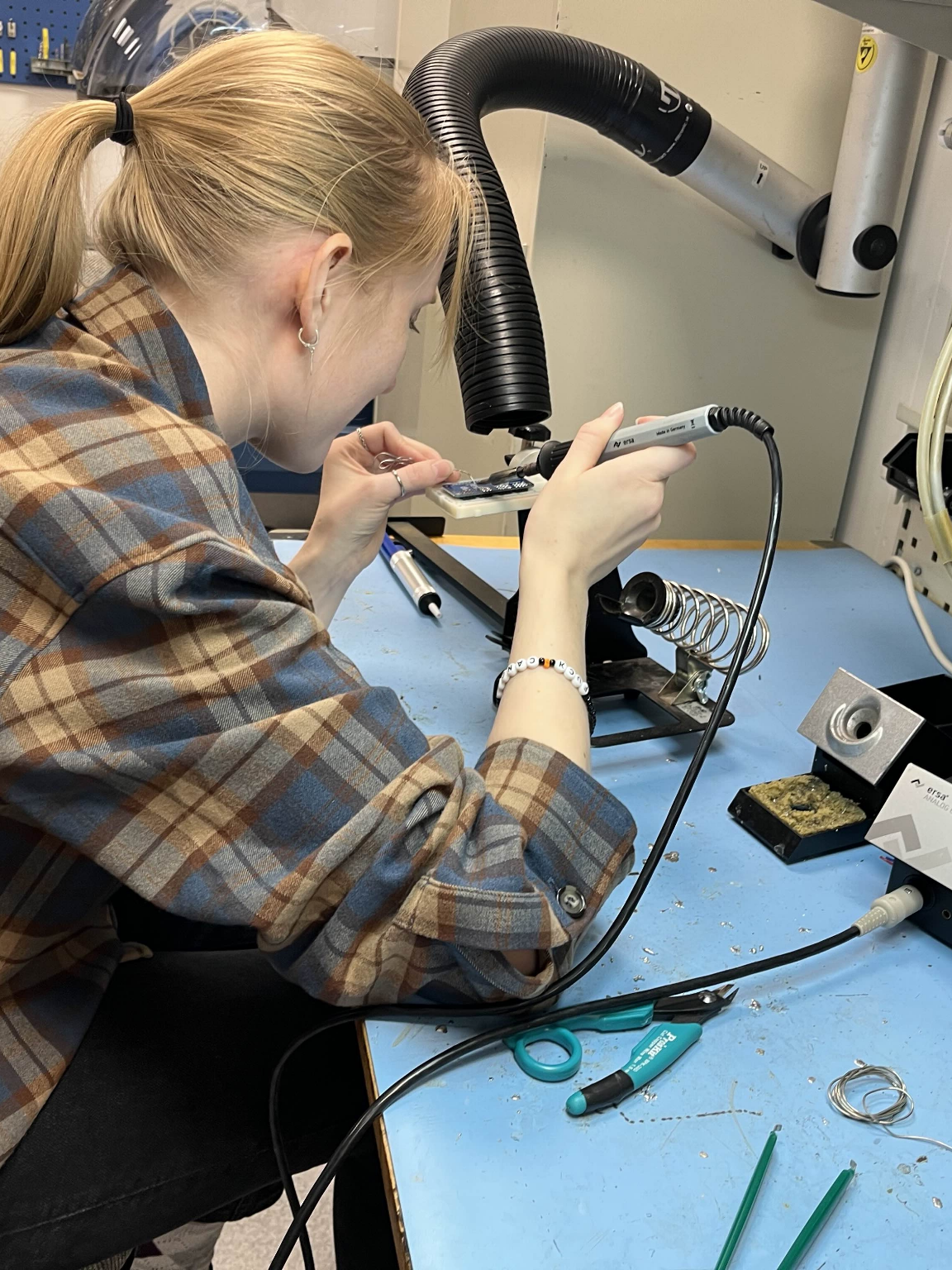
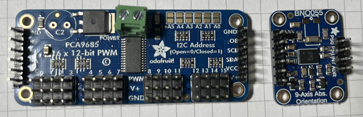
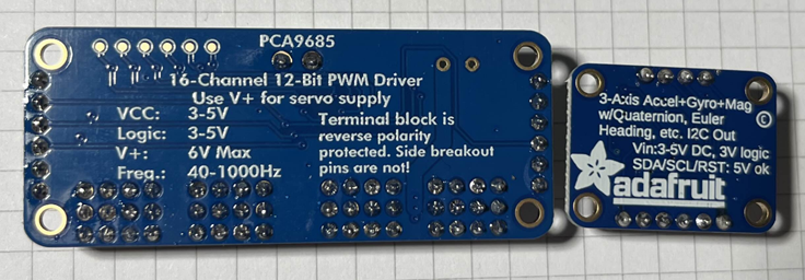
This week has been busy. Monday we had our first presentation, and other than that I have been a bit preoccupied with assignments from other subjects. When we met up on Thursday Sondre had some components he just received that we are going to test out, so I did some soldering. I don’t have a lot of experience soldering, and I haven’t done it in a few years, so I got some help to set it up and run through the basics from Ivan (From Hydroplant Subsystems – Smart Systems group). He gave me a run through of the basics and gave me some tips on how to solder correctly, and additionally how to check if the pins are correctly soldered. He soldered 2 pins to show me and I did the rest, then he gave me feedback. I did a visual test, but for next week I need to test the components to make sure they work. Furthermore we are planning to test the motors next week. We were originally planning on switching the motors to some with encoders, but we are waiting for updates from Steven on that note. Here are some pictures from the soldering and the result.
Robin
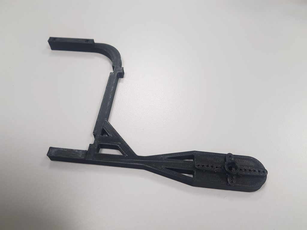
I was in France for two weeks, and I took the opportunity to run my tests with my 3D printer. I therefore have a new 3D version of the arm, but this time one that works with inserts.

The inserts will be fitted into the print to fasten the different parts together. I have thus adapted the print so it can accommodate the said inserts.
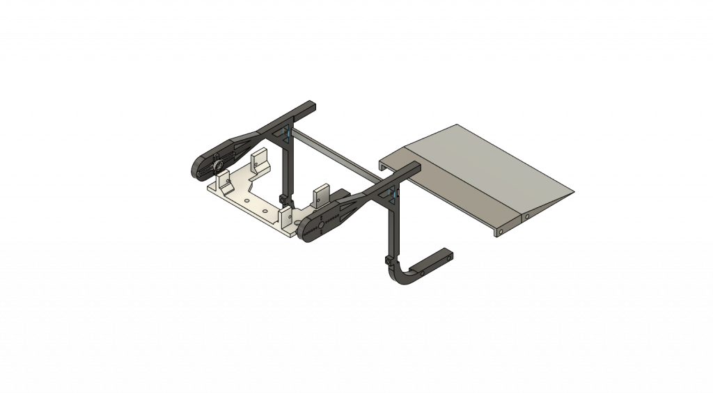
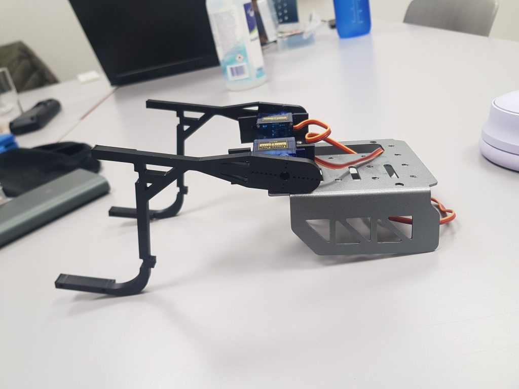
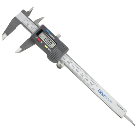
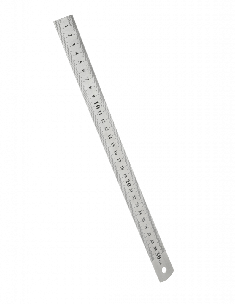
The biggest difference compared to previous weeks is that I now use a ruler and a caliper to take measurements, and therefore my margin of error is much lower than before.
Matias:
This week I had a small setback — I lost one of my project files. It was frustrating, but it made me realize how important it is to keep regular backups and stay organized to avoid losing progress in the future.
In parallel, I’ve been working on the step-down converter for the batteries. The goal is to reduce the input voltage from 11 V down to 5 V to safely power the control electronics. I’ve been learning about voltage regulation and how to ensure stable output while minimizing losses. Even though it wasn’t the most productive week, it turned out to be a valuable one in terms of learning and problem-solving.
Leave a Reply
You must be logged in to post a comment.