Wang
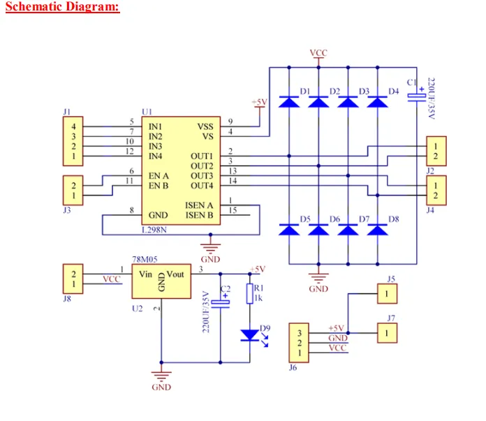
So this week we have now replaced the “DFRobot Driver Expansion Board DFR0548” with the “BBC micro:bit GPIO T-shape breakout board micro:bit GPIO extension shield” and “AZ-L298N”. The reason for this choice was because a lot of time was spent trying to get the car to drive forward without any results. So this week with the new system, the goal is to get it to drive forward. The disadvantage of this switch is that there are a lot more cables to keep track of, which can lead to other problems going forward, such as maybe the cable having poor contact or the cable being damaged or we place wrong pins. The advantage now is that the new T-shape we got is better for prototyping and has standard connection pins. This makes it easier for, say, a beginner to code something to then get the motors to run since here you have direct access to all GPIO pins. The disadvantages now are that the DFR0548 is better for building more complete and larger projects with servos, sensors and motors, and we now lose many of the extra functions that came with the board.
Plan
So for now the plan is still to use Zephyr. We know that the car should run as was shown to us via the use of ADA code. So now we just have to achieve the same thing but now with the use of the Zephyr environment.
On Friday we made a small decision that the goal is still to get the code part working so that it should run forward, and that should be with the use of Zephyr. But now just so that we can move forward, we have managed to get it running by using Arduino code on the micro:bit.
There were some problems with one wheel not wanting to run. It turned out that pin 9 was broken, so now it has been switched to pin 10 so that all wheels are now moving.
Here is the car driving straight ahead. The logic for the car will come soon when we attach sensors and so on. I’m unsure whether we will create the logic right away with Zephyr or if it will first be prototyped and thought out in Arduino. Since there is someone in the group who has gotten something through and possibly managed to get Zephyr working, it will be easier to get others on it as well. There was also talk of some Docker, but those are things that will be set up more for next week, but for now the car is moving.
User Manual
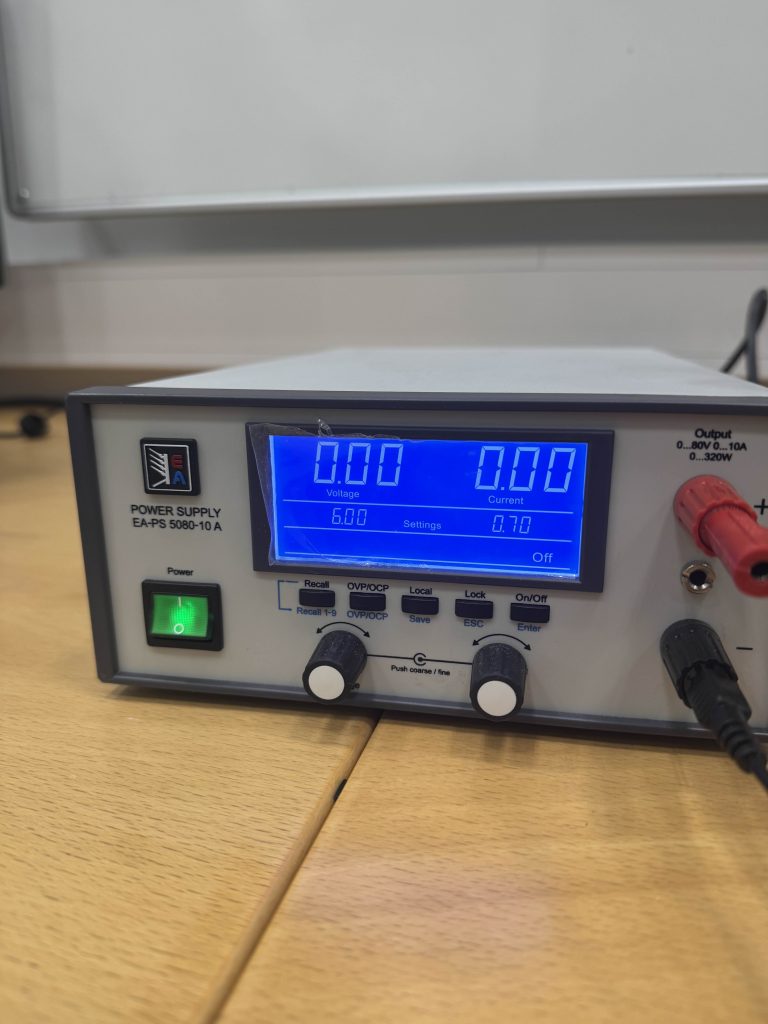
- No. 1
- On and off button for power supply
- No. 2
- Amount of voltage it sends out. Don’t increase it before 100% sure the car can handle it. LET IT STAY AT 6V!!!!!!!
- No. 3
- Amount of current being sent out. SAME THING AS no. 2.
- No. 4
- On and off button for when power is sent out and not sent out without having to turn off and on the entire power supply.
- No. 5
- Controls voltage
- No. 6
- Controls current
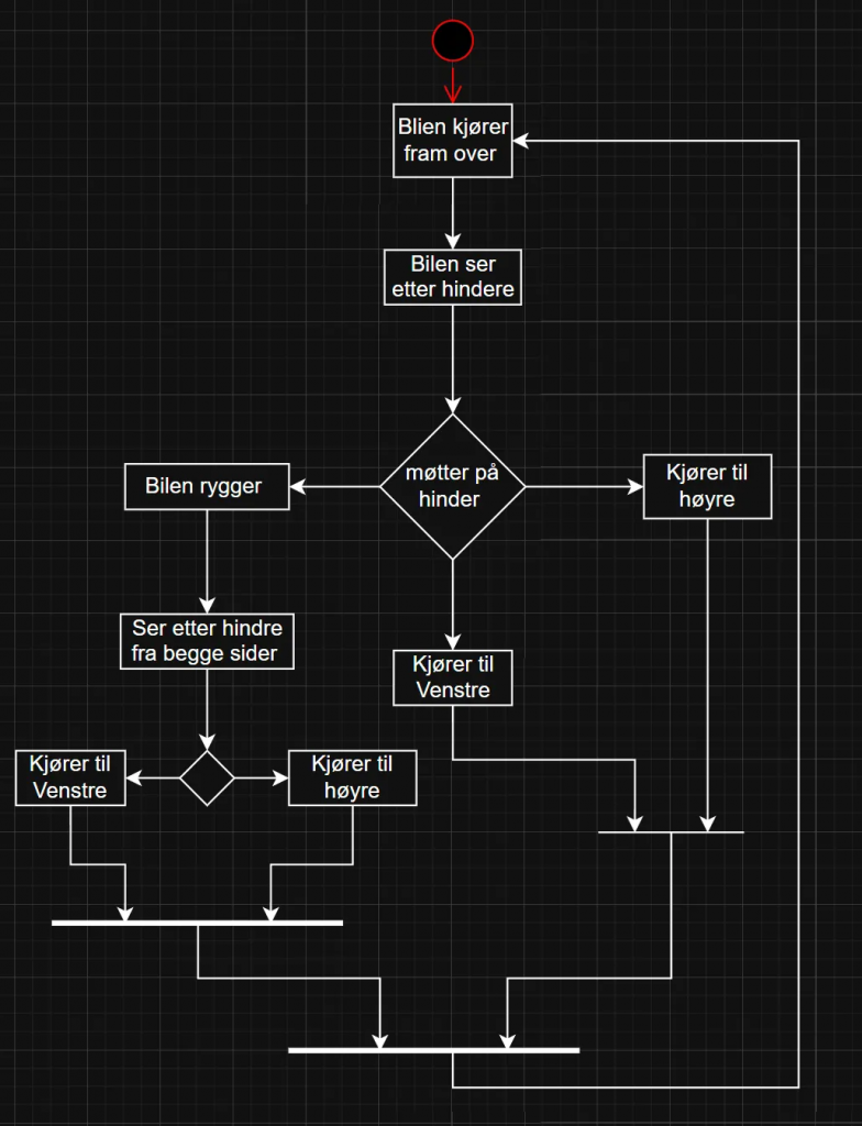
Basic overview of the start-up logic”
Pin Overview
| P0 | ENA | ENA 2 |
|---|---|---|
| P1 | ENB | ENB 1 |
| P2 | ENB | ENB 4 |
| P3 | ENA | ENA 3 |
| P4 | ||
| P5 | ||
| P6 | IN3 | motor 3 A |
| P7 | IN4 | motor 3 B |
| P8 | IN8 | motor 4 B |
| P9 | ||
| P10 | IN3 | motor 4 A |
| P11 | ||
| P12 | IN3 | motor 1 A |
| P13 | IN4 | motor 1 B |
| P14 | IN3 | motor 2 B |
| P15 | IN4 | motor 2 A |
| P16 | ||
| P17 | ||
| P18 | ||
| P19 | ||
| P20 |
This is a very simple code just to get the car to drive straight ahead. Later I’m thinking of using more best practices for the code so that it becomes easier to add things and keep things tidy as the code gets bigger and there are more things to be added.
#include <Arduino.h>

// put function declarations here:
int myFunction(int, int);

// --- Motor 1 (Right Front) ---
const int motor1_A = 12; // IN3
const int motor1_B = 13; // IN4
const int EN1_motor = 1; // ENB

// --- Motor 2 (Left Front) ---
const int motor2_A = 15; // IN3
const int motor2_B = 14; // IN4
const int EN2_motor = 0; // ENB

// --- Motor 4 (Right Back) ---
const int motor4_A = 10; // IN3
const int motor4_B = 8; // IN4
const int EN4_motor = 3; // ENB

// --- Motor 3 (Left Back) ---
const int motor3_A = 6; // IN3
const int motor3_B = 7; // IN4
const int EN3_motor = 2; // ENB

// Function to control Motor 1
void motor1Control(int speed) {
  digitalWrite(motor1_A, HIGH);
  digitalWrite(motor1_B, LOW);
  analogWrite(EN1_motor, speed);
}

// Function to control Motor 2
void motor2Control(int speed) {
  digitalWrite(motor2_A, HIGH);
  digitalWrite(motor2_B, LOW);
  analogWrite(EN2_motor, speed);
}

// Function to control Motor 3
void motor3Control(int speed) {
  digitalWrite(motor3_A, HIGH);
  digitalWrite(motor3_B, LOW);
  analogWrite(EN3_motor, speed);
}

// Function to control Motor 4
void motor4Control(int speed) {
  digitalWrite(motor4_A, HIGH);
  digitalWrite(motor4_B, LOW);
  analogWrite(EN4_motor, speed);
}

void setup() {
  Serial.begin(115200);

  // Set pins for Motor 1
  pinMode(motor1_A, OUTPUT);
  pinMode(motor1_B, OUTPUT);
  pinMode(EN1_motor, OUTPUT);

  // Set pins for Motor 2
  pinMode(motor2_A, OUTPUT);
  pinMode(motor2_B, OUTPUT);
  pinMode(EN2_motor, OUTPUT);

  // Set pins for Motor 3
  pinMode(motor3_A, OUTPUT);
  pinMode(motor3_B, OUTPUT);
  pinMode(EN3_motor, OUTPUT);

  // Set pins for Motor 4
  pinMode(motor4_A, OUTPUT);
  pinMode(motor4_B, OUTPUT);
  pinMode(EN4_motor, OUTPUT);
}

void loop() {
  Serial.println("Running all motors forward at full speed!");

  // Control all motors
  motor1Control(255); // Full speed
  motor2Control(255);
  motor3Control(255);
  motor4Control(255);

}

// put function definitions here:
int myFunction(int x, int y) {
  return x + y;
}
Henning
Finally i managed to overcome the wall that i have been struggling with for two whole weeks. I managed to get the code to work and connect the AI through an API key. What i needed to do was making an account at OpenAI –> Make a project –> Create an API Key –> Add in some money to the project in order to activate the AI –> Insert the API key as an environment variable in my code –> Code was running as shown in the videos below.
First video shows the basic GUI of what i`m trying to achieve for the car. Now the two buttons are both functional and will be under continuous improvements in the upcoming weeks.
Firstly, I had only setup the code as a really basic chat window. So i could only chat with the AI where it could only reply to simple questions. Its able to solve mathematics equations, tell me about different kinds of history, and most importantly, it has the ability to map out mazes with provided information (shown in the video above).
Later i was able to add an “Send image” button to the chat. This button allows me to now take a local picture on my computer, send it to the AI as a file, and it will describe the picture. This is helpful as it can therefore have more visualization and precision to the type of maze it would map out (as the video below shows here).
Last video displays the “Show data” button. Its really basic at this stage as i have mainly been focusing on the AI, and i still have lots of testing to do. But to briefly explain how the code is setup; right now it should be able to track the sensors data through Serial COM port, which is not optimal as the computer would have to be physically connected to the car at all times in order to register the data. I have just set it up as a physical solution now for testing only. Later i will change it to be able to access the data through Raspberry PI.
All in all, this week has opened a lot of roads for me personally. The big wall that was stopping me for a while is finally gone and i can keep on evolving the AI to hopefully be able to either send me a mapped picture back, or at least draw me a picture of a mapped maze. I also need to add a storage/memory to the AI, as it now does not remember previous conversations.
Oskaras
This week we started with changing our car from the Expansion board that used I2C signals to two H bridge drivers (L289N) This was to ease the burden on us since programing with the signal proved to be a little to difficult. the furthest we got was to get a connection with the driver board. Now we only have to worry about GPIO pins which is a lot easier and now we have a lot more control over the car.
So i had a very “fun” time with zephyr. Where it just stopped working out of the blue and gave me thsse two error constantly. I tried many various ways of trying to fix it. I went back to the tutorial installasjon to try to discover the issue. no luck. I even reinstalled the SDK and toolchain completely fresh but the error persisted.
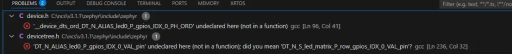
I then went back a couple of versions and got it to a stable working condition. My hypothesis on what went wrong is that while implementing my original code and assigning the pins and designating them i made a mistake there, but the config placed itself outside of the scope of the normal zaphyr files hence why the re-install didn’t work
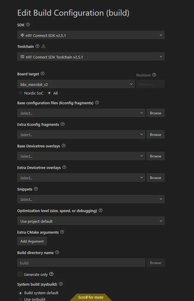

updated the firmware of the microbit to support J-link. This was done by holding the reset button while plugging in the microbit to a micro-usb and entering maintanence mode. afterwards the firmware is dragged to the folder and the microbit takes care of the rest. I’ve also discovered that if it dosent get a valid firmaware it will just stay in mainatance with no going back. lucly it protects itself from complete hard lock and can be fixed if the correct firmware is presented.
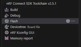
So that i can use the flash button since the extension mainly supports J-link
I really liked the ABC setup from the mid term presentation so i transfered most of the backlog we had for the scrum over to an ABC setup
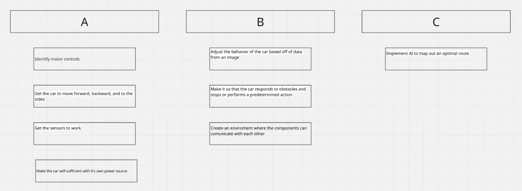
This is just to gave an overview over important milestones as we will still be using sprints as we proceed.
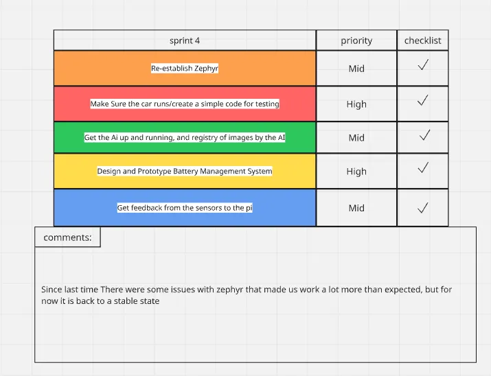
All the tasks were completed this time
Øivind
I can see my blogpost from week 6 is in part missing, so this post will be “a bit” more informative than the last. Including ideas I have discarded through iterations.
Monday – Mid presentation and access to CAVE.
Tuesday -Cross group meeting in the CAVE. Delivering stuff for models of lava tunnels I want to use for the track we will drive on
Wednesday-Batteries assembled and ready for welding. Studying how to control a DC motor with feedback from encoder. PID – Proportional Integrate Derivative – something I learn about in Feedback control of dynamic systems.
Thursday- First some “breadboarding” to get a better view of space needed for the electrical components, then Lab exercise in control of DC motor. Later, I draw and assembled some parts for the mechanical system.
Friday-Meeting with the others in Gruppe 7 in the Cave, then Lecture in Real-Time systems where I asked about Kalman filter, something I will present to the group.
After our presentation and after listening to the other groups, it dawned on me that my work should be better documented. Due to my lack of PCB skill, I have focused on the car as a whole and pulled what I consider important as the needs have surfaced. And making the car without PCBs is possible but not optimal. I am afraid I have been misinterpreted in just focusing on shelf-ready components, and to some extent, that is true. I watched Great Scott on YouTube as advised by Steven early in the course, and since he concluded, just like me, that to buy a BMS was the better option.
Since I started with a top-down approach for the car, most plans are made. Now I am working on how I will regulate the car through feedback. This was the first thing I worried about, and either misinformation or lack of understanding, that was a major concern of mine since I needed sensors to send data back to the logic. I stated this early in the course and talked with both Steven and Richard about the solution for an RPM sensor. Since optical versions are sensitive to dust, I wanted a Hall effect sensor from the start. After iterations on solutions I found them to be hard to implement since I made up my own version that was something between the existing optical and the Hall effect sensors that exist for the motors we are going to use.
I know that now, because Tuesday I met a guy from another group, and we shared some ideas and troubles. That was when I was told that the motors will have Hall effect sensors mounted. This makes parts of my last blogpost resolved. I can now focus on the regulation and explore options for modular PCBs.
Zardasht
Week 6-7-8 :
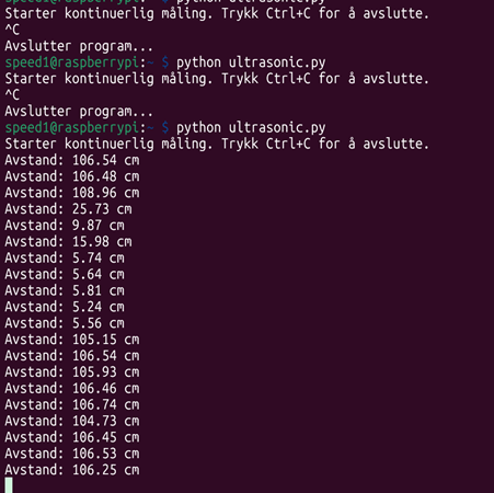
My Weekend Project: Ultrasonic Sensor and Camera Integration
The past two weeks have been very busy for me. Because of autumn break and exams, I didn’t have much time to work on my project. But this weekend, I finally managed to focus and make good progress with my Raspberry Pi.
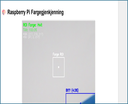
It was very interesting to test the ultrasonic sensor and get it running. It took me a while to start it correctly, but after some trial and error, I figured it out. When it comes to the camera, I found it more difficult. It doesn’t always work as expected, and the accuracy is low. I tried many different ways to measure and improve it.
My goal was to run both the ultrasonic sensor and the camera together on one server, so I could see the data — like distance, color, and object shape — all in one place. I learned that the camera and ultrasonic sensor need to work together to give better results. Even though the ultrasonic sensor is not 100% precise, it works well enough for basic measurements.
After many attempts and testing different methods, I spent over 13 hours this weekend working on it. On some days, I just watched videos and read articles to understand how to reach my goal. It was a challenging but very rewarding experience.