Hello and welcome back!👋
This week has been a busy one for the team, with most of us preparing for the midterm presentation while still pushing our project forward. Despite the focus on presentation work, we still managed to make progress on multiple fronts!
Fredrik:
This week, much of my attention has gone to the midterm presentation, making sure we represent what the group has accomplished in a short amount of time. However, some progress has been made on the project regardless. Earlier, we determined that we should have a proof of concept ready this week. Based on the result of this, we would determine if we move forward with the pump and valve based hydraulic system, or if we revert back to syringes and linear actuators.
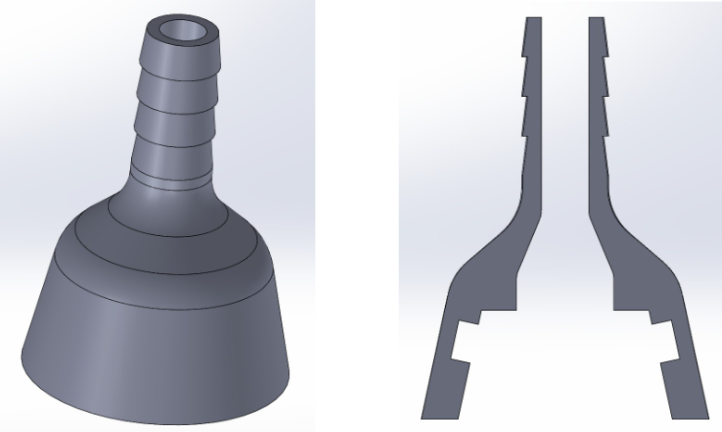
To test the hydraulic cylinder, we require attachment to the pump. I designed an adapter between the pump and the tube, printed from PETG and with an o-ring inside. Images of this are shown below.
The video below shows the result of the hydraulic cylinder test. We connected a tube to one of the chambers of the cylinder and to the pump, and the pump to a reservoir as well. When we turned on the pump, the cylinder piston moved, and the cylinder held together. This is great news, and shows the system works as intended! Due to this success, we are confident that we could make this hydraulic system work, and will be moving forward with this.
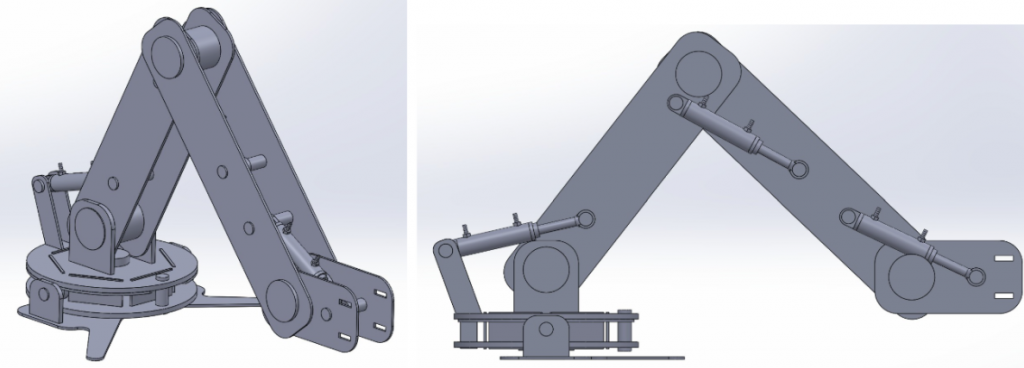
This week I also worked on defining the length and placement of joints and arm segments. Defining this will enable us to start simulating the arm using inverse kinematics. When defining the layout, I tried to get the most movement while also limiting the max reach. This is because the further the arm reaches, the more torque we will have to accommodate for, and the less stable the arm becomes. I also figure that the more movement we get, the greater stress will be put on the cylinder. This might be something we need to revisit later. The temporary layout for now consists of arm segments that are 350 and 400mm long, and cylinders that have a reach of about 40mm. With this, we get a linear reach of about 210mm, which should suffice for our project.
While defining the layout, I made a preliminary design of the arm made mostly from plates that could be lasercut. After discussing with the group, we concluded that design changes was necessary, especially to the base of the structure. Therefor, this design will change before the end of the sprint, but it serves as a good visualization of what we are trying to accomplish. The images of the 3d-model with the layout and preliminary design is shown in the image below.
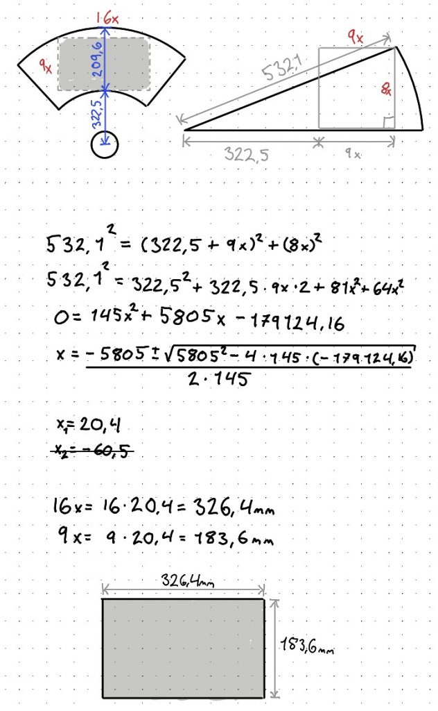
Seeing as the arm rotates around a center, the linear reach of 210mm would not translate directly to a rectangular area, but more similar to a sector. Since the images we will draw will likely be in a rectangular format, we wanted to see what size we could realistically draw within. Choosing an aspect ratio of 9:16, we calculated that we would have an actual drawing area of 326.4mmx183.6mm. This should be more than enough for our project
Lisa:
This week, I spent some time preparing for our midterm presentation, as well as continuing to explore different sensor options for our setup. After last time tests with the TF luna and HC-SR04, I also tried out a new type of sensor combination; A small laser module paired with a photoresistor.
Setting up on the breadboard was quite straightforward, and the readings worked surprisingly well once everything was calibrated. The sensor reacted instantly whenever the laser beam was interrupted. Under, I’ll include a short video of the Arduino setup in action!
So far, the ultrasonic sensor seems the most promising option, especially for measuring short distances with decent accuracy. I will still keep an open mind as we continue testing and comparing the different approaches. Trying out this optical setup also gave some useful insights into how light-based sensors could be used for fast detection tasks.
On a side note, I’ve been a bit less available this week since I’ve been focusing on preparing for my re-exam, but I’ll be back to full speed soon!
Next week, I’ll start focusing on extrapolating the angle of the potentiometer, which will be an important step toward refining our motion feedback and control system.
Syver:
I’ve gotten back on track after being sick this week, so I have finally been able to put in some work again! This week, I’ve tweaked the GUI codebase a bit, making some minor changes there. However, I’ve mainly helped with implementing the protocol that the Raspberry PI will use to transfer the 3-axis coordinates to the Arduino.
Starting out, we established the GitHub repo for kinematics. This will hold the .ino file, running on the Arduino. Link: GitHub repo for kinematics
Lisa’s research into suitable mediums for data transfer from Raspberry Pi to the Arduino gave a good foundation for the implementation, finding USB to be the way to go. I started by testing the serial connection between python (w/ pyserial) and the Arduino. I encountered a few different challenges, stemming from broken cables to broken Arduino, but worked through it in the end.
With the connection established, I worked on getting proof that the transferred data is exactly as it was before transfer. To do this, I implemented a very simple XOR checksum, taking each byte and XORing with a stored initial 0. After a bit of trickery, it worked, and the checksums matched.
I thought this would be more straightforward than it ended up being, but in the struggle, I learned some points about how we should implement the system.
Starting out, we wanted to generate the coordinates as G-code commands, then transfer all of it to the Arduino at job start. This would make it more straightforward in that the Arduino has all the data and can fully control the process of iterating through them. This turned out to be a bad way to do things, mainly because of two things.
Firstly, the Arduino has 8kB of dynamic memory, giving us a ceiling of approximately 300 lines of G-code. This is way too little for a whole image sequence. Secondly, giving the Arduino all the data at once diminishes its purpose as a single-purpose embedded system. Ideally, the Arduino should only handle execution of motion, and the Raspberry Pi should handle feeding it coordinates continually.
Based on this, it seems the best way to implement the interface is to allocate a 256B queue structure on the Arduino. In total, this gives us space to store 10 commands with 4 digit coordinate precision. The Arduino can send a ping when it has 5 commands left in the queue, prompting the RPI to send 5 more. This seems like the cleanest way to implement the interface.
With this, we have in total tested each step in the chain User <-> RPI <-> Arduino, with Arduino -> Valves and Arduino <- JointPositionSensors in focus going forward. To test these interfaces, we need to mock up a simulation, so we can start testing the PIDs for each piston. This will most likely be my main focus the coming week.
( No visuals from me this week, please do check out our GitHub repos for all the code 🙂 )
Emory:
This week I didn’t have much time, as most of the week I have focused on retake exams and the midway presentation. Still, I did start by looking into how I can make the coordinates I got from the image and make them into g-code so it will be easier for the robot arm to be able to draw from them.. Since g-code is used by CNC machines and 3D printers, it seems very fitting to use it for our purpose too.
So I started with learning a bit about g-code so I could recognise what the setup of that is to make sure when I get my coordinates into that, it would look correct. It does involve a lot of just fixing the start point of where it’s going to trace, and up and down movements between which, for what we make, would be the polygon coordinates.
I did find someone who has done something similar, which I am taking inspiration from on github. But their starting point is different, where they take the raw image from and convert it like I have in previous codes, inside the same code, where they then turn it into g-code. So I do learn a lot from seeing how they did it and how I can do it differently since I have a different starting point.
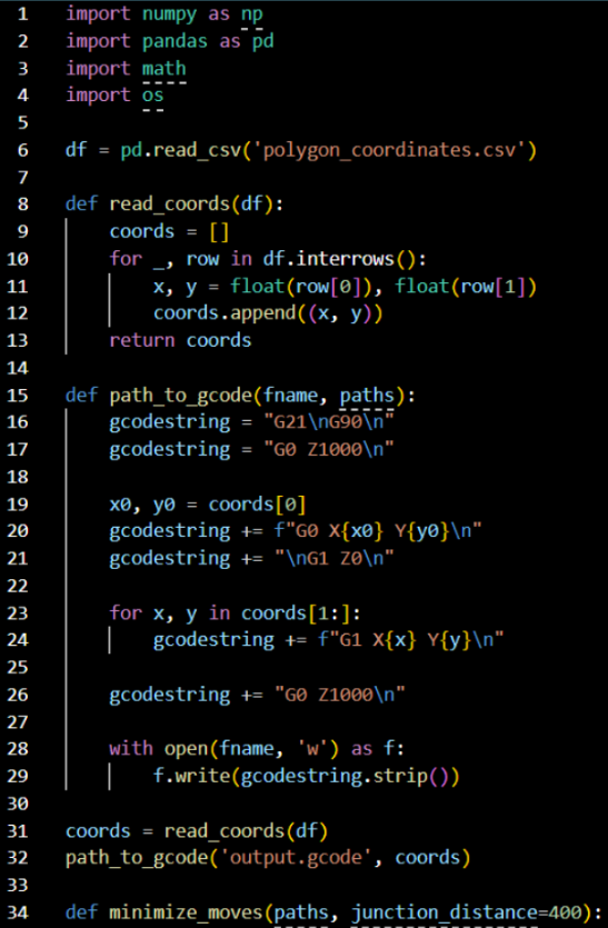
I did start on setting up the code for converting the coordinates from the polygons into g-code, but so far it hasn’t gotten far and isn’t runnable yet and just a very basic setup on what I can use to continue it. It starts by reading the coordinates from the csv file that is being created from the earlier code. So will have to further learn about how to convert into g-code so I can continue fixing the code into what we need.
Erling:
Some small carryover illness.
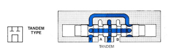
This week i have continued the research on the 4/3 valves. Bane of my existence as they are.
We did some testing and proof of concepting for our hydraulic systems main components in order to run a GO/NOGO cutoff for the “realistic” hydraulic solution for the arm. The choice is between an actual hydraulic system as described in earlier blog posts, and syringes as linear actuators driven by stepper motors individually. After some discussion, We landed on GO for the more complex hydraulic solution. This might be the more difficult of the two ways to go, but we deem it worth continuing development.
I realized that for the health of our water pump, a 4/3 valve with a bypass center would be the ideal choice because then the pump flow wouldn’t stop, which would cause damage to it over time. I attempted to modify my 3D-printed valve design to allow for a bypass center rather than a pressure center, however after looking into how this kind of valve actually looks on the inside i determined, after attempting to model it, that it is not suitable for 3d print at the scale and pressures that we are looking to work in. Sealing of the shaft to the housing for a bypass center design would be a nightmare.
As we can see in the proof of concept test videos, the valve design that we ended up with testing leaked profusely, even with o-rings sized to match the application.
after further simulation in FESTO Fluidsim, i discovered that i was wrong, and that bypass center valves would not work for us without even more flow control equipment, due to the fact that the pistons would not be able to build any pressure because all the other valves connected to the manifold would be connected directly to the tank when in the neutral position.
Because of this, we decided it is best to use closed center valves, and turn the pump off and on with a relay to avoid damage to it. In general damage to the pump shouldn’t be an issue, as at least one of the cylinders should be in motion most of the time. The pump realistically only needs to be turned off when the arm is not meant to be moving.
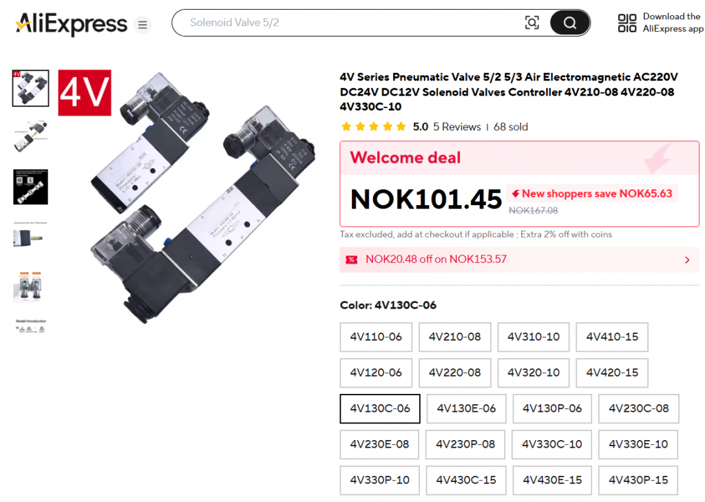
We agreed as a group to spend our 500 NOK budget on valves from Aliexpress after being satisfied with the proof of concept for the hydraulic system solution.
That’s all for now, see you next week!