This week our group was a bit smaller than usual, since not everyone could be there. On Monday, those of us who were present focused on finishing up the presentation for next week. We went through the slides together, divided the speaking parts, and made sure the overall structure was okay.
After that, we discussed the progress of the robot and what we should focus on moving forward. We tested the robot with the micro:bit setup, but we quickly realized that something wasn’t working as expected with the way it was moving. The motion was inconsistent and didn’t really match what we wanted. Because of this, we agreed that we will need to get hold of the new motors with encoders, since having precise feedback from the motors is important if we want the robot to drive accurately and reliably. Once we get these motors, testing them will be an important next step.
Two of us also talked about the possibility of making further upgrades, like moving away from the micro:bit to a more powerful microcontroller. This would open up more options for autonomy and better control. Doing this will also give the electrical engineering students more tasks, since moving to a new platform would involve designing and setting up additional hardware. These changes will of course depend on if we have time, but it is becoming clear that the current setup is only a starting point, and both hardware and software need to be improved if we want the robot to perform well in the long run.
Théo:
This week I succeeded in having a feed back from the 4 sensors on the car, and printing the first letter of the capteur sending the smallest distance.
#include <Arduino.h>
#include <Adafruit_Microbit.h>
Adafruit_Microbit microbit;
struct Sensor {
const char *name;
int trigPin;
int echoPin;
char letter; // lettre à afficher
};
Sensor sensors[4] = {
{“Back”, 1, 0, ‘B’}, // Back : Trig P1, Echo P0
{“Front”, 14, 16, ‘F’}, // Front: Trig P14, Echo P16
{“Left”, 13, 12, ‘L’}, // Left : Trig P13, Echo P12
{“Right”, 15, 2, ‘R’} // Right: Trig P15, Echo P2
};
const unsigned long PULSE_TIMEOUT = 30000UL; // ~30 ms -> ~5 m
const float SOUND_SPEED_CM_PER_US = 0.0343f;
const unsigned long BETWEEN_MEAS_MS = 60;
const uint8_t B_bmp[5] = {
B11100,
B10010,
B11100,
B10010,
B11100
};
const uint8_t F_bmp[5] = {
B11111,
B10000,
B11110,
B10000,
B10000
};
const uint8_t L_bmp[5] = {
B10000,
B10000,
B10000,
B10000,
B11111
};
const uint8_t R_bmp[5] = {
B11110,
B10001,
B11110,
B10100,
B10010
};
const uint8_t X_bmp[5] = {
B10001,
B01010,
B00100,
B01010,
B10001
};
void setup() {
Serial.begin(115200);
delay(50);
microbit.begin();
microbit.matrix.begin();
microbit.matrix.clear();
for (int i = 0; i < 4; ++i) {
pinMode(sensors[i].trigPin, OUTPUT);
digitalWrite(sensors[i].trigPin, LOW);
pinMode(sensors[i].echoPin, INPUT);
}
Serial.println(“=== Multi-HC-SR04 : lecture 4 capteurs ===”);
for (int i = 0; i < 4; ++i) {
Serial.print(“Capteur “); Serial.print(i);
Serial.print(” = “); Serial.print(sensors[i].name);
Serial.print(” TRIG=”); Serial.print(sensors[i].trigPin);
Serial.print(” ECHO=”); Serial.println(sensors[i].echoPin);
}
Serial.println(“—————————————–“);
}
unsigned long measurePulseUs(int trigPin, int echoPin) {
digitalWrite(trigPin, LOW);
delayMicroseconds(2);
digitalWrite(trigPin, HIGH);
delayMicroseconds(10);
digitalWrite(trigPin, LOW);
unsigned long d = pulseIn(echoPin, HIGH, PULSE_TIMEOUT);
return d;
}
float pulseUsToCm(unsigned long pulseUs) {
if (pulseUs == 0) return -1.0f;
return (pulseUs * SOUND_SPEED_CM_PER_US) / 2.0f;
}
void showLetter(char c) {
switch (c) {
case ‘B’: microbit.matrix.show(B_bmp); break;
case ‘F’: microbit.matrix.show(F_bmp); break;
case ‘L’: microbit.matrix.show(L_bmp); break;
case ‘R’: microbit.matrix.show(R_bmp); break;
default: microbit.matrix.show(X_bmp); break;
}
}
void loop() {
float distancesCm[4];
// mesurer chaque capteur séquentiellement (évite interférences)
for (int i = 0; i < 4; ++i) {
unsigned long pulse = measurePulseUs(sensors[i].trigPin, sensors[i].echoPin);
float dcm = pulseUsToCm(pulse);
distancesCm[i] = dcm;
Serial.print(sensors[i].name);
Serial.print(” (“);
Serial.print(sensors[i].letter);
Serial.print(“) -> “);
if (dcm < 0) Serial.println(“timeout”);
else {
Serial.print(dcm, 1);
Serial.println(” cm”);
}
delay(BETWEEN_MEAS_MS); // petit délai entre capteurs
}
int bestIdx = -1;
float bestDist = 1e9;
for (int i = 0; i < 4; ++i) {
float d = distancesCm[i];
if (d > 0 && d < bestDist) {
bestDist = d;
bestIdx = i;
}
}
if (bestIdx >= 0) {
Serial.print(“Capteur le plus proche = “);
Serial.print(sensors[bestIdx].name);
Serial.print(” (“);
Serial.print(sensors[bestIdx].letter);
Serial.print(“) : “);
Serial.print(bestDist, 1);
Serial.println(” cm”);
showLetter(sensors[bestIdx].letter);
} else {
Serial.println(“Aucun écho valide (timeout sur tous).”);
microbit.matrix.show(X_bmp); // afficher X si rien
}
Serial.println(“—————————————–“);
delay(300); // pause avant prochaine passe
}
After this, I took my code and Sondre’s code for the wheel and I tried to merge these two, asking the car to move forward if it detected something in front turn right.
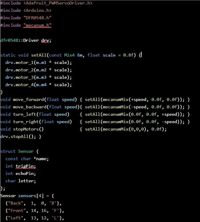
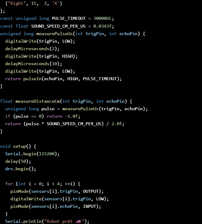
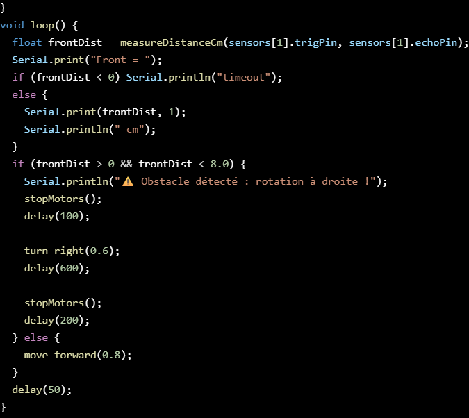
But at this point, Sondre and I realized that we were working on the same thing but Sondre knows more about the wheels than I do so he will keep working on this and I’ll start working on the communication between two micro:Bit.
Sondre:
This week went mostly into research and less into actual coding, so I didn’t really move much forward with the program itself. The robot is moving with the micro:bit and the driver board, and it can read some sensor data, but I can see that this setup won’t really be good enough for the final version. The micro:bit is fine for testing, but it doesn’t have the power or flexibility we need for things like encoders and better autonomy plus controlling the pickup arm. Even though its not been to much coding this week, I have done some tweaking of the code so that the detection is a bit more reliable. It does detect walls and turns as you can see in this video:
@https://youtu.be/wW-TKKevjBA
So I’ve been looking into other options and also bought some new components that would be worth to try out. This includes an ESP32, some TB6612FNG motor drivers, a PCA9685 servo driver, and a BNO055 orientation sensor. My thought is that the ESP32 could be the main controller since it has way more power and better support, but I’ve also thought about maybe using the Pico as a helper if needed, for example just to deal with the encoders and motors. The motor drivers should give us better control of the wheels, and the servo driver will make it easier to run the arm.
I have tried making the esp32-c6 microcontroller work with VS code and platform IO. But since this chip is relatively new it does not support the Arduino framework yet. It only supports ESP-IDF. This means that if we wanted to keep this controller we would need to learn a new framework. Instead I have ordered another controller from the esp32 series which does support the Arduino framework. In the meantime I have tried to understand the raspberry pico. This controller does not support direct upload from VS code, but instead I have to create a .uf2 file, and manually upload it to the board. This is a bit more work when changing the code. But since the Pico does not have a dedicated USB-to-serial programmer built in, it cannot receive code directly over a COM-port reset. Instead it appears on the computer as a USB stick. When I then drag the file onto it, the firmware is then written into the flash memory.
I did a little testing on this with a blinking light code:
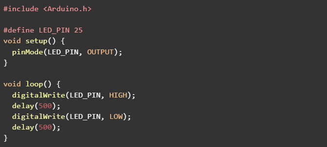
This showed me that it worked, but I did not spend much time on this since this board will only be used if necessary. Since the esp32 should have enough pinouts to all the different parts and enough power.
Besides that, I’ve also been working on the group presentation for Monday. We finished the slides together and I’ve practiced what I’m going to say.
So overall, not a lot of coding progress this week, but I think the research and new parts will help us make the robot more solid if we get the time to switch over.
Anette:
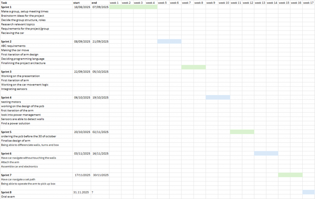
This week I have been working on and researching power management systems, and I have been looking into the further upgrades mentioned in the beginning. We have also been working on the presentation, and I finished the roadmap with our sprints as shown under.
Matias:
This week I was away and didn’t have the possibility of doing too much, I focused on adding the capacitors to the circuit and learning how to choose the right types and values for each part. It helped me understand better why certain capacitors are used in specific places and how they affect the circuit’s performance.