Wang
This week there hasn’t been much focus on the project due to account exams. The code logic to get the car to start driving is well underway together with the distance sensor. The car hasn’t been able to drive yet using Zephyr, but it does run with Ada code and the distance sensor used in the other project that has the same car.
This week and next, I will have little time to work much on the project because of the account tests.
How to work with Devicetree Visual Editor
https://docs.google.com/document/d/11IXEAOeEb7_dCMOqLLH4vVTUHFcYyUNieQWqt3716vs/edit?tab=t.0
Get the car to move
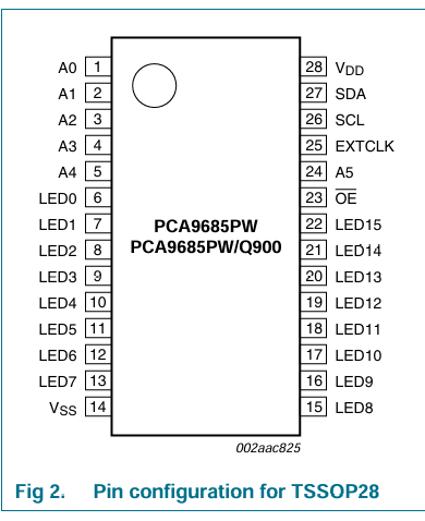
To get the car to drive, the plan is to use the Zephyr environment. The car uses DC motors that are connected to a driver expansion board (V2.0) DFR0548.
To get in contact with the motors, we need to use pins 20 and 19.
Zephyr setup on VS Code
To set up the Zephyr environment, we followed the Google Docs document “CS4120-1 24V” that we received from Lecturer “Steaven Bos”.
- Step 1 The first thing we had to do was download the nRF Connect SDK and VS Code. So we followed the instructions from this page: Exercise 1 – Installing nRF Connect SDK and VS Code – Nordic Developer Academy First, you need to download SEGGER J-Link and VS-code if you don’t already have it. Then inside VS-code you need to add “nRF Connect for VS Code Extension pack”
- Step 2 If you have followed everything correctly up to this point, you can go to nRF Connect Create a new application. Then you will be taken to the search field where you can type “nRF LED matrix sample” which will give you an example where the LEDs on the micro:bit should start to light up and show some different patterns. But before it runs, you must first go down to “Applications” then down to build and then you need to specify that you are using micro:bit. Search for “bbc” and it will come up. Then you can open the terminal in VS Code by right-clicking on build and you will get a window with info, then select “start new Terminal Here”. Then to start the program you type “west build” then “west flash” or you can just type “west flash” If you want to see the activity, you can download “Serial monitor” for VS Code.
How to code
So now that everything should be set up, it should be time to code this.
When you set up an empty project in Zephyr, it creates some folders and files for you automatically. Your main code should be located in src as a main.c file. At the same level as you find the src folder, you will also see the prj.conf file and CMakeList.txt
- prj.conf This file is the project’s main configuration file. Since Zephyr is a very large library of drivers, protocols, and core functions. So for it to be as efficient and small as possible, it will only include what you specifically ask for.
- CMakeList.txt This is the build instructions for the project. prj.conf is the one that tells which parts CMakeList.txt needs.
- GPIO (General Purpose Input/Output)
- PWM (Pulse Width Modulation)
- It tells the strength of current it sends out.
- I2C (Inter-integrated Circuit)
- SPI (Serial Peripheral Interface)
The communication between the DFR0548 board and micro:bit v2 is via the I2C protocol. So by using Zephyr’s I2C API, you can establish communication with the DC motors.
Micro:bit driver expansion board (V2.0) uses the PCA9685PW chip.
https://docs.rs-online.com/8054/0900766b80f65101.pdf
Code
//bbc_microbit_v2.overlay

&i2c0 {
    status = "okay";

    pca9685: pca9685@40 {
        compatible = "nxp,pca9685-pwm";
        reg = <0x40>;
        #pwm-cells = <2>;
        status = "okay";
        label = "PCA9685";
    };
};

/ {
    aliases {
        pwm-driver = &pca9685;
    };
};
//prj.conf

# I2C støtte (nødvendig for PCA9685)
CONFIG_I2C=y

# PWM støtte
CONFIG_PWM=y

# PCA9685 PWM driver
CONFIG_PWM_PCA9685=y

# Logging og debugging
CONFIG_PRINTK=y
CONFIG_LOG=y

# Øk stack størrelse hvis nødvendig
CONFIG_MAIN_STACK_SIZE=2048

# GPIO støtte (for eventuell knappekontroll)
CONFIG_GPIO=y
Test main.c from Gemini AI to see if it gets any contact with the DC motors.
#include <zephyr/kernel.h>
#include <zephyr/device.h>
#include <zephyr/drivers/i2c.h>
#include <zephyr/drivers/pwm.h>
#include <zephyr/sys/printk.h>

// PCA9685 I2C address (standard er 0x40 for DFR0548)
#define PCA9685_I2C_ADDR 0x40

// Motor kanaler på PCA9685 - basert på DFR0548 skjema
// Motor 1 (U2/HR8833): LED0-LED3
#define M1_IN1_CHANNEL 0   // LED0 -> AIN1
#define M1_IN2_CHANNEL 1   // LED1 -> AIN2
#define M1_PWM_CHANNEL 2   // LED2 -> Enable (nSLEEP høy for å aktivere)

// Motor 2 (U3/HR8833): LED4-LED6
#define M2_IN1_CHANNEL 4   // LED4 -> AIN1
#define M2_IN2_CHANNEL 5   // LED5 -> AIN2
#define M2_PWM_CHANNEL 6   // LED6 -> Enable (nSLEEP høy for å aktivere)

// PWM verdier (0-4095 for 12-bit PCA9685)
#define PWM_MAX 4095
#define PWM_OFF 0

// Motor hastigheter
#define SPEED_SLOW 2048    // 50% hastighet
#define SPEED_MEDIUM 3072  // 75% hastighet
#define SPEED_FAST 4095    // 100% hastighet

// Hent PWM device
static const struct device *pwm_dev;

// Funksjon for å sette PWM på en kanal
int set_channel_pwm(uint8_t channel, uint16_t value) {
    uint32_t pulse_us;
    int ret;

    // Konverter 0-4095 verdi til mikrosekunder (20ms periode for PCA9685)
    // PCA9685 har 20ms periode (50Hz), så full PWM = 20000us
    pulse_us = (value * 20000) / 4096;

    ret = pwm_set(pwm_dev, channel, PWM_USEC(20000), PWM_USEC(pulse_us), 0);
    if (ret < 0) {
        printk("Feil ved setting av PWM på kanal %d: %d\\n", channel, ret);
        return ret;
    }

    return 0;
}

// Funksjon for å kontrollere motor 1
void motor1_control(bool forward, uint16_t speed) {
    // Først aktiver motor med nSLEEP høy
    set_channel_pwm(M1_PWM_CHANNEL, PWM_MAX);

    if (forward) {
        // Fremover: IN1=HIGH, IN2=LOW
        set_channel_pwm(M1_IN1_CHANNEL, speed);
        set_channel_pwm(M1_IN2_CHANNEL, PWM_OFF);
    } else {
        // Bakover: IN1=LOW, IN2=HIGH
        set_channel_pwm(M1_IN1_CHANNEL, PWM_OFF);
        set_channel_pwm(M1_IN2_CHANNEL, speed);
    }
}

// Funksjon for å kontrollere motor 2
void motor2_control(bool forward, uint16_t speed) {
    // Først aktiver motor med nSLEEP høy
    set_channel_pwm(M2_PWM_CHANNEL, PWM_MAX);

    if (forward) {
        // Fremover: IN1=HIGH, IN2=LOW
        set_channel_pwm(M2_IN1_CHANNEL, speed);
        set_channel_pwm(M2_IN2_CHANNEL, PWM_OFF);
    } else {
        // Bakover: IN1=LOW, IN2=HIGH
        set_channel_pwm(M2_IN1_CHANNEL, PWM_OFF);
        set_channel_pwm(M2_IN2_CHANNEL, speed);
    }
}

// Bevegelse funksjoner
void drive_forward(uint16_t speed) {
    printk("Kjører fremover\\n");
    motor1_control(true, speed);
    motor2_control(true, speed);
}

void drive_backward(uint16_t speed) {
    printk("Kjører bakover\\n");
    motor1_control(false, speed);
    motor2_control(false, speed);
}

void turn_left(uint16_t speed) {
    printk("Svinger til venstre\\n");
    motor1_control(false, speed);  // Venstre motor bakover
    motor2_control(true, speed);    // Høyre motor fremover
}

void turn_right(uint16_t speed) {
    printk("Svinger til høyre\\n");
    motor1_control(true, speed);    // Venstre motor fremover
    motor2_control(false, speed);   // Høyre motor bakover
}

void stop_motors(void) {
    printk("Stopper motorer\\n");
    // Sett alle kanaler til OFF
    set_channel_pwm(M1_IN1_CHANNEL, PWM_OFF);
    set_channel_pwm(M1_IN2_CHANNEL, PWM_OFF);
    set_channel_pwm(M1_PWM_CHANNEL, PWM_OFF);
    set_channel_pwm(M2_IN1_CHANNEL, PWM_OFF);
    set_channel_pwm(M2_IN2_CHANNEL, PWM_OFF);
    set_channel_pwm(M2_PWM_CHANNEL, PWM_OFF);
}

int main(void)
{
    int ret;

    printk("\\n========================================\\n");
    printk("Starter micro:bit bil med DFR0548\\n");
    printk("Motor driver board V2.0\\n");
    printk("========================================\\n\\n");

    // Vent litt for å la systemet stabilisere seg
    k_msleep(1000);

    // Hent PWM device (PCA9685)
    pwm_dev = device_get_binding("PCA9685");
    if (!pwm_dev) {
        printk("FEIL: Kunne ikke finne PCA9685 PWM device!\\n");
        printk("Sjekk at I2C er aktivert og devicetree overlay er riktig.\\n");
        return -1;
    }

    printk("PCA9685 PWM driver funnet og klar!\\n");

    // Test at vi kan sette PWM på alle kanaler
    printk("Tester PWM kanaler...\\n");
    for (int i = 0; i < 7; i++) {
        ret = set_channel_pwm(i, PWM_OFF);
        if (ret < 0) {
            printk("Kunne ikke initialisere kanal %d\\n", i);
        } else {
            printk("Kanal %d OK\\n", i);
        }
    }

    printk("\\nStarter motor test sekvens om 2 sekunder...\\n");
    k_msleep(2000);

    // Test sekvens
    while (1) {
        printk("\\n--- Kjører fremover ---\\n");
        drive_forward(SPEED_SLOW);
        k_msleep(3000);

        printk("\\n--- Stopper ---\\n");
        stop_motors();
        k_msleep(1000);

        printk("\\n--- Kjører bakover ---\\n");
        drive_backward(SPEED_SLOW);
        k_msleep(3000);

        printk("\\n--- Stopper ---\\n");
        stop_motors();
        k_msleep(1000);

        printk("\\n--- Svinger venstre ---\\n");
        turn_left(SPEED_SLOW);
        k_msleep(2000);

        printk("\\n--- Stopper ---\\n");
        stop_motors();
        k_msleep(1000);

        printk("\\n--- Svinger høyre ---\\n");
        turn_right(SPEED_SLOW);
        k_msleep(2000);

        printk("\\n--- Stopper ---\\n");
        stop_motors();
        k_msleep(3000);

        printk("\\n=== Test sekvens ferdig, starter på nytt ===\\n");
    }

    return 0;
}
After a lot of troubleshooting, I have found out that the PCA9685 was not at address 0x40 but at 0x70. I have now also managed to get contact with the serial monitor in VS Code. The car is still not running.
The new prj.conf
# prj.conf - Enkel konfigurasjon med direkte I2C

# Serial
CONFIG_SERIAL=y
CONFIG_CONSOLE=y
CONFIG_UART_CONSOLE=y
CONFIG_PRINTK=y

# I2C
CONFIG_I2C=y

# GPIO
CONFIG_GPIO=y

# Stack
CONFIG_MAIN_STACK_SIZE=2048
The new bbc_microbit_v2
// bbc_microbit_v2.overlay

&i2c0 {
    status = "okay";

    // PCA9685 PWM controller på adresse 0x70
    pca9685: pca9685@70 {
        compatible = "nxp,pca9685-pwm";
        reg = <0x70>;
        #pwm-cells = <2>;
        status = "okay";
        label = "PCA9685";
    };
};
New main.c from AI to just quickly see if it now has any contact.
// main.c - Direkte I2C kontroll av PCA9685 på adresse 0x70
#include <zephyr/kernel.h>
#include <zephyr/device.h>
#include <zephyr/drivers/i2c.h>
#include <zephyr/sys/printk.h>
// PCA9685 registre
#define PCA9685_MODE1 0x00
#define PCA9685_MODE2 0x01
#define PCA9685_PRESCALE 0xFE
#define PCA9685_LED0_ON_L 0x06
#define PCA9685_LED0_ON_H 0x07
#define PCA9685_LED0_OFF_L 0x08
#define PCA9685_LED0_OFF_H 0x09
// I2C adresse (funnet av scanner)
#define PCA9685_ADDR 0x70
// Motor kanaler
#define M1_IN1 0 // LED0
#define M1_IN2 1 // LED1
#define M1_EN 2 // LED2
#define M2_IN1 4 // LED4
#define M2_IN2 5 // LED5
#define M2_EN 6 // LED6
static const struct device *i2c_dev;
// Skriv til PCA9685 register
int pca9685_write_reg(uint8_t reg, uint8_t value) {
uint8_t buf[2] = {reg, value};
return i2c_write(i2c_dev, buf, 2, PCA9685_ADDR);
}
// Les fra PCA9685 register
int pca9685_read_reg(uint8_t reg, uint8_t *value) {
return i2c_write_read(i2c_dev, PCA9685_ADDR, ®, 1, value, 1);
}
// Sett PWM på en kanal (0-4095)
void set_pwm(uint8_t channel, uint16_t on, uint16_t off) {
uint8_t reg_base = PCA9685_LED0_ON_L + 4 * channel;
i2c_reg_write_byte(i2c_dev, PCA9685_ADDR, reg_base, on & 0xFF);
i2c_reg_write_byte(i2c_dev, PCA9685_ADDR, reg_base + 1, on >> 8);
i2c_reg_write_byte(i2c_dev, PCA9685_ADDR, reg_base + 2, off & 0xFF);
i2c_reg_write_byte(i2c_dev, PCA9685_ADDR, reg_base + 3, off >> 8);
}
// Initialiser PCA9685
int init_pca9685(void) {
uint8_t mode1;
int ret;
printk("Initialiserer PCA9685 på adresse 0x%02X\\n", PCA9685_ADDR);
// Les MODE1 register
ret = pca9685_read_reg(PCA9685_MODE1, &mode1);
if (ret < 0) {
printk("Kunne ikke lese fra PCA9685: %d\\n", ret);
return ret;
}
printk("MODE1 register: 0x%02X\\n", mode1);
// Reset (sleep mode)
pca9685_write_reg(PCA9685_MODE1, 0x00);
k_msleep(10);
// Sett prescale for 50Hz (for motorer)
pca9685_write_reg(PCA9685_MODE1, 0x10); // Sleep
pca9685_write_reg(PCA9685_PRESCALE, 121); // ~50Hz
pca9685_write_reg(PCA9685_MODE1, 0x00); // Wake up
k_msleep(10);
pca9685_write_reg(PCA9685_MODE1, 0x20); // Auto increment
printk("PCA9685 initialisert!\\n");
return 0;
}
// Motor kontroll
void motor1(bool forward, uint16_t speed) {
printk("Motor 1: %s, hastighet: %d\\n", forward ? "FREM" : "BAK", speed);
// Enable motor
set_pwm(M1_EN, 0, 4095);
if (forward) {
set_pwm(M1_IN1, 0, speed);
set_pwm(M1_IN2, 0, 0);
} else {
set_pwm(M1_IN1, 0, 0);
set_pwm(M1_IN2, 0, speed);
}
}
void motor2(bool forward, uint16_t speed) {
printk("Motor 2: %s, hastighet: %d\\n", forward ? "FREM" : "BAK", speed);
// Enable motor
set_pwm(M2_EN, 0, 4095);
if (forward) {
set_pwm(M2_IN1, 0, speed);
set_pwm(M2_IN2, 0, 0);
} else {
set_pwm(M2_IN1, 0, 0);
set_pwm(M2_IN2, 0, speed);
}
}
void stop_all(void) {
printk("Stopper alle motorer\\n");
for(int i = 0; i < 16; i++) {
set_pwm(i, 0, 0);
}
}
int main(void)
{
int ret;
k_msleep(2000);
printk("\\n\\n****************************************\\n");
printk("* DIREKTE I2C KONTROLL AV PCA9685 *\\n");
printk("****************************************\\n\\n");
// Hent I2C device
i2c_dev = DEVICE_DT_GET(DT_NODELABEL(i2c0));
if (!device_is_ready(i2c_dev)) {
printk("I2C device ikke klar!\\n");
return -1;
}
printk("I2C device klar\\n");
// Test om PCA9685 er der
uint8_t test;
ret = pca9685_read_reg(PCA9685_MODE1, &test);
if (ret < 0) {
printk("Fant ikke PCA9685 på 0x%02X!\\n", PCA9685_ADDR);
printk("Feilkode: %d\\n", ret);
return -1;
}
printk("✓ PCA9685 funnet på 0x%02X!\\n", PCA9685_ADDR);
// Initialiser PCA9685
ret = init_pca9685();
if (ret < 0) {
printk("Initialisering feilet!\\n");
return -1;
}
// Nullstill alle kanaler
stop_all();
printk("\\nStarter motortest om 3 sekunder...\\n");
printk("Sjekk at motorene er koblet til M1 og M2!\\n");
k_msleep(3000);
uint16_t speed = 2048; // 50% hastighet
while (1) {
printk("\\n=== TEST RUNDE ===\\n");
// Test motor 1
printk("\\nMotor 1 fremover...\\n");
motor1(true, speed);
k_msleep(2000);
printk("Motor 1 bakover...\\n");
motor1(false, speed);
k_msleep(2000);
stop_all();
k_msleep(500);
// Test motor 2
printk("\\nMotor 2 fremover...\\n");
motor2(true, speed);
k_msleep(2000);
printk("Motor 2 bakover...\\n");
motor2(false, speed);
k_msleep(2000);
stop_all();
k_msleep(500);
// Begge sammen
printk("\\nBegge fremover...\\n");
motor1(true, speed);
motor2(true, speed);
k_msleep(3000);
printk("\\nStopper...\\n");
stop_all();
k_msleep(2000);
}
return 0;
}
Øivind
(Almost) Complete Robot Car Parts List
- 6× XTAR 18650 2600mAh 30A Li-ion cells – Battery cells, main energy source :ETA 8/10
- 6-slot 18650 holder with brass contacts – Temporary battery holder for prototyping :Wang
- Nickel strips (pure nickel 0.15–0.2mm) – For spot-welding cells into a permanent pack ETA 12-18/10
- Spot welder (mini portable welder) – For welding nickel strips to battery terminals ETA 12-18/10
- 3S 30–40A BMS with balancing – Protects batteries from overcharge, overdischarge, short circuit, balances cells ETA 12-18/10
- Balance leads + JST-XH 4-pin connector – Wires to connect cell taps to the BMS for balancing ETA 12-18/10
- 20A automotive blade fuse + holder – Main fuse for safety, prevents fire from short circuits: Henning
- DC rocker switch / XT60 loop-key – Main disconnect switch for battery: Borrowed of Steven
- Heat shrink tubing + Kapton tape – For insulation and safe battery pack assembly
ETA 12-18/10
- DC-DC Buck Converter (LM2596 / MP1584) – Steps down battery voltage (12.6V) to 5V for Raspberry Pi & sensors :In stock
- Pololu 5V 3A Step-Down Regulator – Stable 5V power for Raspberry Pi ETA 12-18/10
- 3.3V LDO regulator – For sensors/microcontrollers requiring 3.3V ETA 12-18/10
- L298N Dual H-Bridge Boards (x2) – Motor drivers for 4 DC motors 1 in stock, the rest ETA 12-18/10
- Alternative: BTS7960 motor drivers (x2) – More efficient option for motor driving ETA 12-18/10 Ordered as option
- 4× 6–12V gear motors with wheels – Drives the wheels of the robot ETA 12-18/10
- Pololu Magnetic Encoder Kit or Alps Encoder – Wheel speed feedback (motion sensing)
- 1000µF electrolytic capacitor (per motor driver) – Smooths motor supply voltage, reduces noise: Henning
- TVS diode (12V) – Transient protection against motor spikes: Henning
- Raspberry Pi 4 or Zero 2 W – Main controller for navigation & AI :In stock
- BBC micro:bit or Arduino Nano – Optional microcontroller for motor/sensor tasks In stock
- 4–6× HC-SR04 Ultrasonic sensors – Obstacle detection around the car In stock, more coming
- ADS1115 ADC Modules (x2) – High-precision analog input converters for sensors ETA 12-18/10
- MPU6050 / MPU9250 IMU – Gyroscope + accelerometer for orientation ETA 12-18/10
- Optional: Pi Camera Module 3 – Vision system for advanced navigation In stock
- 0.1µF ceramic capacitors – Decoupling for sensors and microcontroller :Henning
- Chassis (kit or custom 3D print) – Physical base of the robot: We have two!
- Caster wheel (1–2) – Balance and smooth turning: Not going to use
- M3 standoffs, screws, cable ties, tape – Assembly hardware: Ongoing
- 14–16 AWG silicone wire – High-current wiring for motors and power: Henning
- 22–24 AWG wire – Signal wiring for sensors and logic: Henning
- XT30/XT60 connectors – Battery and motor driver connections ETA 12-18/10
- JST-XH connectors (4-pin) – Balance leads for BMS ETA 12-18/10
- Dupont wires / header pins – Connections between controllers and sensors: Ongoing
- Screw terminal blocks – For secure modular connections: Ongoing
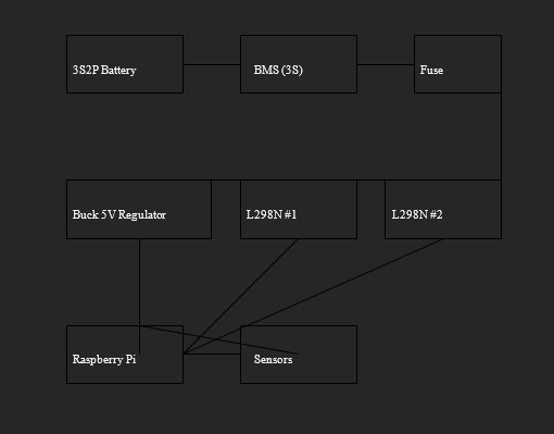
Simple Robot Car Wiring Schematic
What happened to my understanding of what Steven said the first day of this course, when he said: “Execution is King!”?
At least the process has moved forward, nonetheless is this going to be both fun and challenging as the parts arrive, since I know we are going to face obstacles while implementing them and test software with sensors, actuators and motors. I have created a temporary BOM (Bill of materials) for many of the parts I know we are going to use, with comments on what we have acquired, what we have in order and what I will ask Henning for. I will send it to our blogmaster with this post and he will decide how to share the document in the blog.
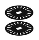
I still have not found these speed encoder wheels for sale other than included in expensive packages, so I will investigate if they are crucial parts we need.
In the part list I included a really simple diagram, without the Arduino and specific sensors we will use, since there will be changes shortly when we switch from micro:bit to Arduino.
One C-prioritized option we are working on is a robotic arm, with DC motor powered drillbit and laser rangefinder on the same disc, with 180 degrees rotation by servo. But before we get deeper into the core functionality of the car, this is slightly on hold. But I can say that the idea is, if we can find a way to map underground either via GPR (Ground penetrating Radar) or Electrical resistivity tomography (ERT) or electrical resistivity imaging (ERI).I’m unsure about seismoacoustic mapping underground, need more research from my side. I read early in this course an article that used seismoacoustic mapping, and found somewhere a picture that visualize a method to test this in practice. I’m afraid I do not follow practice right now, since I cannot site the article, and “steal” a drawing without creditating the person that made it. Anyway, this is a picture of a model that can be used put the car on and check for cavities.
Henning
These last weeks i have been struggling with the same issues as the past! As i have been working with the end side of the project and a new programming language. It has really been a wall to climb. So from my past weeks i have had issues with figuring out how to access OpenAI API keys. In the meantime i have constructed more windows and labels for the data which our sensors will show.

Now for the AI which im trying to make work with the GUI! I have figured out how to access the AI through https://platform.openai.com/chat. All i needed to do was to make an account and create a project through OpenAI. My next goal will be to figure out how to extract the API key and connect it to my code. If i get this up, i will reach a solid end to our project as i can start training the AI to function with our goal.
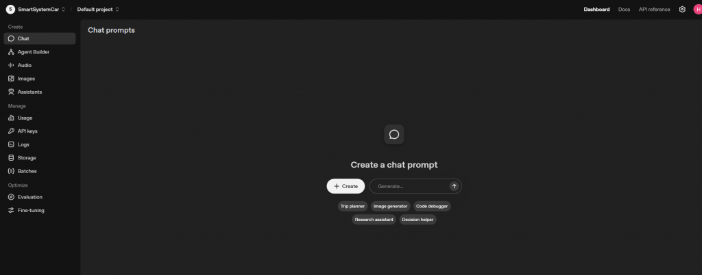
The picture above shows the website of the project i have created so far and the AI itself. This is all through the website and not through the GUI which i`m trying to solve. I am hoping for a result in the next weeks to come.
Unfortunately because of the issues with the code that i currently have, i cannot build the GUI and i can`t show any result of the sensors button yet. Once everything is up and running, i will be able to provide more videos and pictures.
Oskaras
The Week Before Last
This week, we installed Zephyr and managed to communicate with the micro:bit. Then I tried to communicate with the extension board on the car. Here is the code:
C Code (main.c):
C
#include <zephyr/kernel.h>
#include <zephyr/device.h>
#include <zephyr/drivers/pwm.h>

static const struct pwm_dt_spec motor1 = PWM_DT_SPEC_GET(DT_ALIAS(motor-m1));

#define PERIOD_USEC (20 * 1000)
#define DUTY_CYCLE_MAX PERIOD_USEC

void main(void)
{
    if (!pwm_is_ready_dt(&motor1)) {
        printk("Error: PWM device %s is not ready\\n", motor1.dev->name);
        return;
    }

    printk("I2C Motor control starting...\\n");

    /* Run motor forward at 75% speed for 3 seconds */
    printk("Spinning M1 forward at 75%%...\\n");

    uint32_t pulse_width = (DUTY_CYCLE_MAX * 75) / 100;
    pwm_set_pulse_dt(&motor1, pulse_width);

    k_sleep(K_SECONDS(3));

    /* Stop the motor */
    printk("Stopping M1.\\n");
    pwm_set_pulse_dt(&motor1, 0);
}
Project Configuration (prj.conf):
CONFIG_PRINTK=y
CONFIG_I2C=y
CONFIG_PWM=y
CONFIG_PWM_PCA9685=y
Device Tree Overlay (app.overlay):
Kodebit
/ {
    /* Create aliases for our two motors */
    aliases {
        motor-m1 = &motor_m1;
        motor-m2 = &motor_m2;
    };

    /* Define the motors. They are connected to the PCA9685, not the micro:bit directly. */
    motor_m1: motor_m1 {
        compatible = "pwm-motor";
        pwms = <&pca9685 0 0>, /* Motor M1 uses channel 0 (AIN1) and 1 (AIN2) of the PCA9685 */
               <&pca9685 1 0>;
        label = "MOTOR_M1";
    };
    motor_m2: motor_m2 {
        compatible = "pwm-motor";
        pwms = <&pca9685 2 0>, /* Motor M2 uses channel 2 (BIN1) and 3 (BIN2) of the PCA9685 */
               <&pca9685 3 0>;
        label = "MOTOR_M2";
    };
};

&i2c0 {
    status = "okay";

    pca9685: pwm-controller@40 {
        compatible = "nxp,pca9685-pwm";
        reg = <0x70>;
        label = "PCA9685";
    };
};
After a lot of troubleshooting, Zephyr would not cooperate properly, so I hit a wall there that I couldn’t get past. Furthermore, this was the week of the Network and Security exam, so unfortunately, I had to dedicate a good deal of time to that as well.
Last Week:
I mostly worked on the layout for the presentation and reworked some of the tables to make them more presentable. I also started on an “ABC form” for the project, because I felt it might work quite well to represent the goals:
A:
- Identify motor controls
- Get the car to move forward, backward, and to the sides
- Get the sensors to work
- Capture an image and make it available for the micro:bit
B:
- Make it so that the car responds to obstacles and stops or performs a predetermined action
- Adjust the behavior of the car based on the image from the camera
C:
- Implement AI to map out an optimal route
As we saw from the presentation, I got more inspiration and thought that what the others had done was very well-structured and easy to follow, so I am going to work on elaborating on this a bit more, while at the same time continuing with the Scrum methodology I have already started.