Bram van den Nieuwendijk (Mechanical engineer)
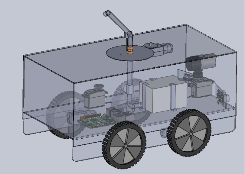
In week 6 I started to look into ways to realize the rotating part of the spraying mechanism. In the 3D model I added the rotating mechanism for the nozzle, and also for the camera. The step for next week is to prepare for the mid-term presentation, and to further detail the spraying mechanism to check the feasebility.
Åsmund Wigen Thygesen
This week I have gotten properly started on the motion control system. This is the code that will control the vehicle components, like wheel motors, servos, sprayer motor, etc.
First things first, the wheels. They will be driven by motors with encoders, so to make our life easier down the line we need to define the distance the wheel moves along the ground for each step of the encoder. This is a simple ratio of the circumference of the wheel and the total encoder steps in one revolution.
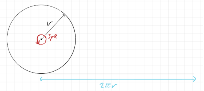
This gives us a simple equation (SpR= steps per revolution)
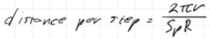
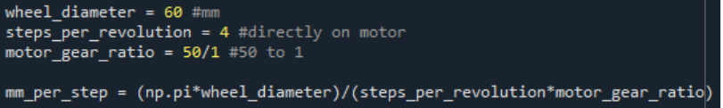
With some extra parameters to make entering the specifics of the motor and wheel easier, we get this. Note that these are just placeholder values.
Next, we want to be able to tell the vehicle to move to any arbitrary position we tell it (within reason of course), this, at least initially, will be achieved by first rotating to face the target position, then driving the distance to the target position.
The angles and distances are found with some simple trigenometry:
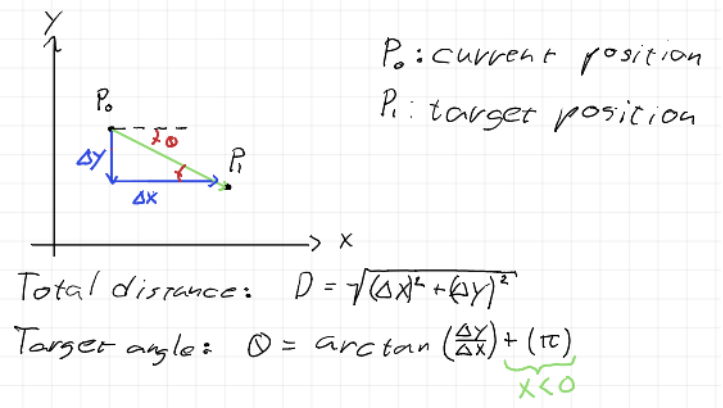
This is pretty easily implemented in a function.

Rotation is handled by repeatedly checking which way to go to reach the angle and rotating the wheels in opposite direction to spin in the correct direction. Then when “close enough” to the desired angle it stops. We get the absolute rotation from a magnometer, measuring the earth’s magnetic field, and acting as a compass.
This method of moving has a few flaws tho, it was selected due to the assumption that wheel slipping would make it hard to do more complicated moves than move straight and rotate. Since our positional data will be relying on the wheel encoders to track how far the vehicle has moved, any wheel slipping while moving will result in our position data drifting. When rotating, this is not as much of an issue since we use the magnometer to get an absolute rotation.
However, there are other problems even if we don’t have wheel slipping. For one the rotation, while absolute, is not perfectly accurate and we cannot possibly perfectly line up the vehicle in the exact orientation we wish to drive. This will also lead to some amount of drift, how much is hard to say and depends mostly on how precise our motor control ends up being. One obvious way to help combat the drifting is to integrate the position based on the actual angle of the vehicle, not the desired angle and just accept ending up at a slightly different location than planned, potentially move again if the error is too great.
We could also make corrections underway, however with the current intended implementation that would require the vehicle to stop for each correction, rather than move continually and adjust the wheel speed individually.
I would like to implement a more dynamic movement system, that would essentially make minor corrections the whole way towards the target, but for now, I’m sticking to this rather simple approach since it should be good enough to meet our A requirements.
Rick Embregts
This wheek the schematic for the overview of the electrical signal is completed and can be seen below.

Most motors in the circuit are supposed to be supplied on 12V but will be run on the battery voltage, which can be a bit higher. Motors degenerate due to thermal influence caused by currents running through the windings. If the motors are current limited, we can probably get away with it and don’t have to add a second 12V converter.
There is also a start being made for the detailed schematic of the MCU (Motor Controll Unit) that will hopefully be done next week.
Darkio Luft
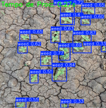
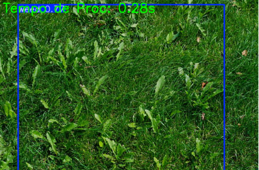
After I trained the model, I actually got some pretty good results for a first run, especially since the dataset was quite small. But that small dataset is definitely the issue. For example, if the image has a green background, the detection misclassified the whole thing as weed. After the presentation next week I’ll work to improve the results.
Sulaf
Overview
Following last week’s deep dive into the requirements and risk analysis I made, this week was about translating those plans into a structured testing strategy when the car is all assembled (after it is 3D printed). While we’re still waiting for the physical components (IMU, wheel encoders, etc.), I wanted to make sure we’re not just waiting passively, so I focused on how we’ll test each subsystem once the hardware arrives, and how we can simulate or prepare in the meantime.
The goal was to break down the robot into its core functionalities and define what success looks like for each part (ideal success), so that when we finally get the components, we can hit the ground running.
Guiding Questions
• How will we test each subsystem?
• What tools or platforms can we use in the meantime?
• What does a successful test look like?
Subsystem Testing Plan
We broke the robot down into six main subsystems and outlined how each will be tested:
| Subsystem | Testing method | Success criteria |
| Navigation (IMU + Encoders) | Simulated path tracking using WOKWI | Robot follows its path with less than 10 cm deviation Obstacle Detection (Ultrasonic) |
| Obstacle Detection (Ultrasonic) | HC-SR04 sensor simulation and physical test | Robot pauses and reroutes when an object is within 10-15 cm |
| Weed Detection (AI Model) | Testing by running using a camera, and test it with the dataset testing and camera input | At least 90% accuracy for detecting weed |
| Spray Mechanism | Manual trigger test to check that it works | Spray activates only when weed is detected within range |
| Power System | Battery pack testing per module | Each subsystem runs independently without instability |
By breaking it down like this, it helps us isolate issues and test each part before full integration of the part. It also gives us flexibility, and if one module is delayed, we can still move forward with others.
Simulation
I expanded our WOKWI simulation to include multiple sensors. While it’s still limited, it helps visualize how the robot will behave in real time. Next I will begin drafting a test script that will run through basic movement and detection logic once the physical robot is ready.
For example, I added a simulated obstacle at 25 cm and tested how the ultrasonic sensor responds. The rerouting logic is still in progress, but the detection part is working as expected.
This week felt like a shift from planning to pre-executing. We now have a clear testing roadmap, a modular strategy we can work with and a way to simulate and test even without hardware. Once the components arrive, we’ll be ready to start physical testing immediately. The project is starting to feel real now, and I’m excited to see how each part comes together.