Hello and welcome back!👋
We’ve just wrapped up another week of Sprint 2. Here’s a look at what each of our team members has been working on last week:
Fredrik:
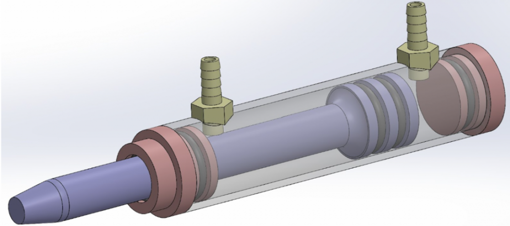
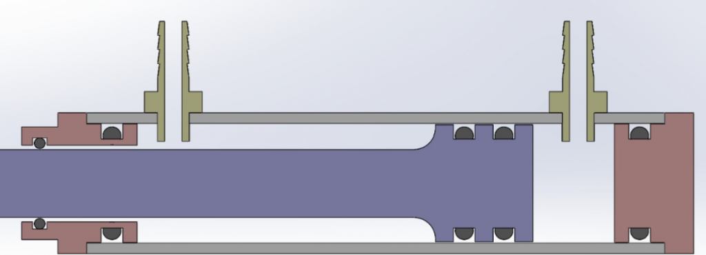
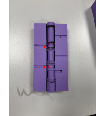
Last week I started designing a hydraulic cylinder, in order to establish a proof of concept for our hydraulic system. This week I mainly focused on tweaking the design such that it can be produced, and actually building the prototype. These design changes included facilitating o-ring attachments, and reducing the amount of sealed interfaces. The final 3d-model of the cylinder is shown in the picture below.
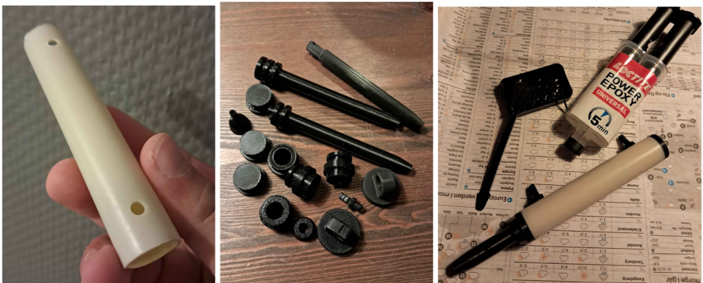
I bought a PVC pipe with a diameter of 20mm to use as the base of the cylinder. With the help of Erling, I cut the pieces into the right length, and drilled holes for the ports. For the 3d-printed parts I decided to use PETG, seeing as it is durable and has less moisture absorption than PLA. I needed some adhesive that worked on both PETG and PVC. After some research, I figured my best option was two-component epoxy glue. This is because it will provide a good bond between the two materials, it provides some gap-filling (the two parts don’t need to be totally flush), and it is easily available to me. This is the first time I have used o-rings for my projects, so it was definitely a learn by failing type of experience. I needed to keep in mind how the o-rings would behave during assembly, while making sure it would still keep a tight seal. This ended up being a highly iterative process, learning something with every iteration.
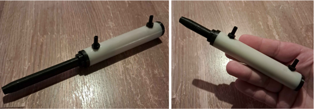
When it was all printed, prepared, and put together, it seemed to work. I have yet to test it fully, but the chambers appear to be sealed, and the structure held together. The cylinder itself has a length of 80mm, and the piston inside the cylinder has a delta reach of 58mm.
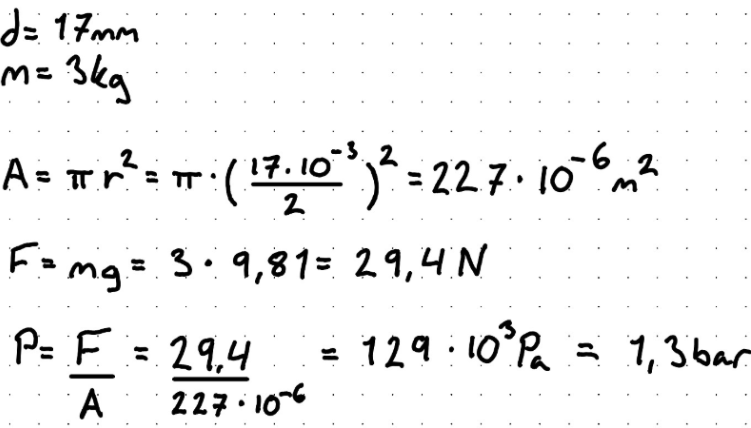
The piston inside the cylinder requires much force to be moved, likely due to the tight fit with the o-rings. To push the piston, roughly 3kg of force is required. The calculations shown in the picture below shows that 1.3 bar is required to push the piston. The pump we have acquired can push up to 9 bar, so this should not be an issue. Next week we will put together the proof of concept for the hydraulic system, hopefully testing if the cylinder works as intended.
Lisa:
Last week I continued working on the proof of concept from the week before. For now, the conclusion is to keep both the Raspberry Pi and Arduino in the system. This creates a clear separation of tasks: the Pi handles planning and interfaces, while the Arduino focuses on real-time motor control. We also had a productive meeting with Steven, where we got some sensors to test out!
Sensor
After a meeting with Steven, I got a couple of distance sensors to test. I wanted to see how well they could perform in our setup, so I wired them up on a breadboard and connected a LCD screen to easily visualize the measurements. Setting everything up went fairly smoothly, though the LCD gave me a bit of trouble at first since no text would show up. After some fiddling I realized the backlight was simply too bright, and once I dimmed it down the readings appeared as expected.
- TF Luna (LiDAR): Worked fine overall, but the minimum range was about 300 mm. That’s not ideal for our needs, since we sometimes need to measure closer distances.
- HC-SR04 (Ultrasonic): This one could measure much closer and seemed more suitable. The readings did fluctuate slightly, with about ±1 mm difference, but overall it felt much more promising.
I filmed both tests, so check out the videos to see how the sensors behaved in practice;
There’s still one more method I want to try out. That will be my focus next week, along with continuing to evaluate the RPi and Arduino split.
Syver:
I have done a lot less than I planned this week, due to sickness.
I did get to research the implementation of a captive portal with nodogsplash early this week, but was not able to implement it. The nodogsplash looks like a fitting tool, I only wish it was more actively developed. The development on their git shows old dates, with dated build instructions and suite, so I got stuck debugging build configurations. I think I am close to finding a solution, though.
I was also able to participate in the discussions around selecting sensor type to provide position feedback to the Arduino, and some other group discussions around design decisions.
During the last weeks I was able to complete the tasks scheduled for the two-week sprint ending today, however most were done in the first week, and not this one one. I could definitely have assigned myself a few more tasks had I not been sick. Once I’ve recovered, I’ll take on what I planned to do this week and the coming one, focusing on nodogsplash, GUI user identification and more GUI elements.
Emory:
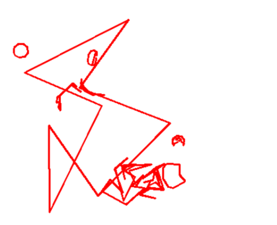
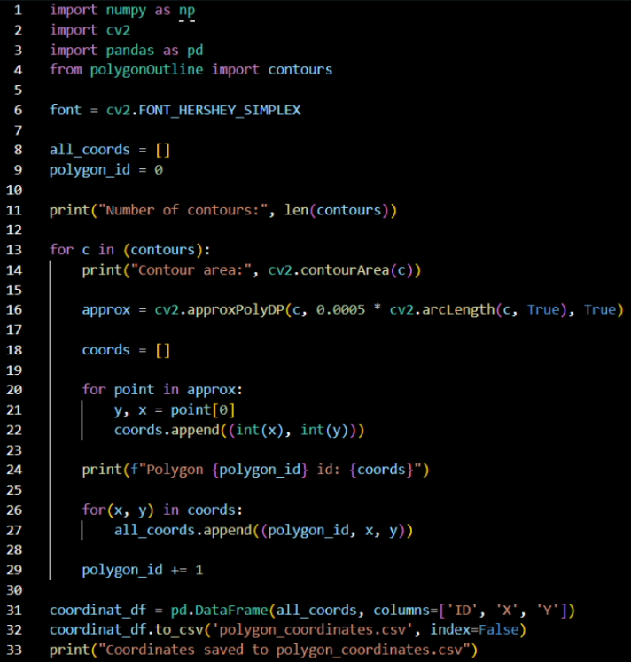
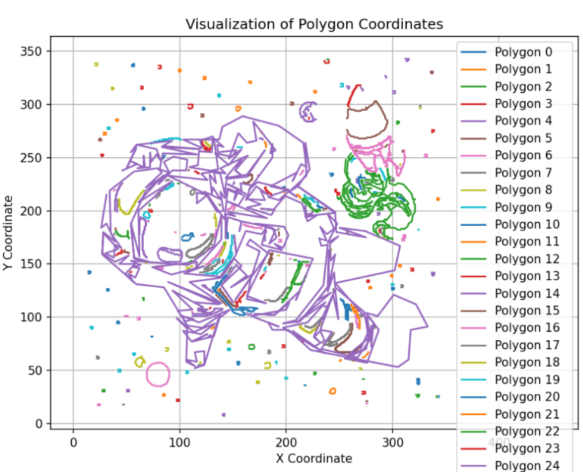
This week, I started by checking what needed to be fixed for the coordinates to be correctly placed and drawn. First thing is that all the coordinates are being connected into one continuous polyline, which explains why the drawing looks like this.
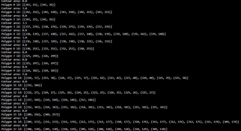
So, I had to start by ensuring the coordinates were grouped into different polylines, allowing the drawing to be fully displayed. So I made it so that each polygon would get its own ID, so that the coordinates could be put into the drawing. I also saw that while working, I had doubled the code for no reason, so I removed the second part that did the same thing. After this, I got a lot more coordinates from the drawing, which seemed more correct. Here’s a small selection of what I got.
Then I made a code just to put the coordinates into to see if they come out correctly, and this is what I got.
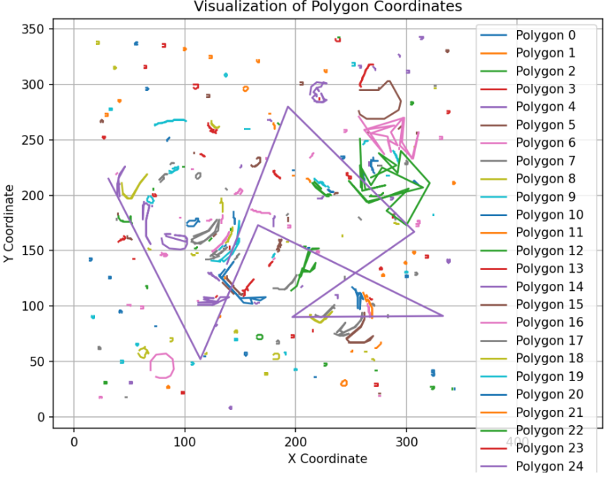
Which was closer but still a bit off on what I wanted. Then realised I had a different accuracy than the code for the polygons*,* which is 0,0005 and here it’s 0,01.
By changing this, I got the result I was looking for. I also flipped the x, y to y, x for the image not to appear upside down.
Now this is a good start for the coordinates that the robot can use to draw from. A possible future improvement of this would be to make it simpler so that the robot doesn’t have to draw more than necessary for the image to be recognisable.
Erling:
This week i have been feeling under the weather, therefore my progress on the project has been a bit lacking.
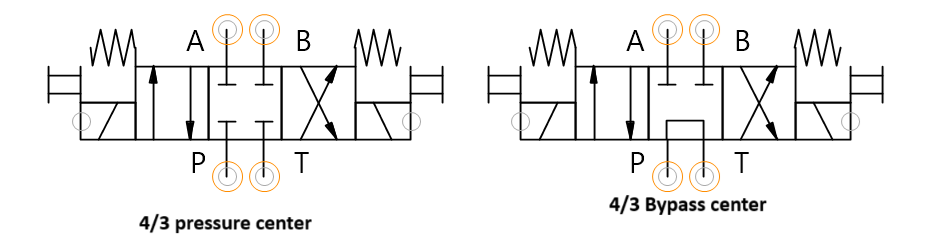
I have modeled and 3Dprinted a version of a 4/3 hydraulic valve for our proof of concept for the system.
A 4/3 valve in hydraulics is a direction control valve that has four ports and three stable states. These come in several variants, the one we need is either a 4/3 pressure center or a 4/3 bypass center. Both will work in our application.
The solution with 4/3 valves was chosen on background of the simulations from the last week as it is the best way for us to control a hydraulic cylinder. This judgement is based on both complexity and on cost. We would like to purchase on borrow these valves as they are very important to our system and need to function without leakage. After hearing with the school, we havent found a source of parts, and decided that in order for our system to work the way we intend and not be too costly, we have to make all the hydraulic equipment by ourselves.
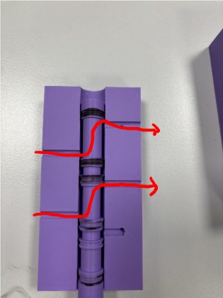
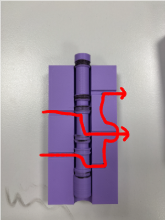
Left to right: forward position, Neutral(pressure) position, Reverse position.
For sealing elements, we are using O-rings from a kit from Biltema that was purchased privately for another project. This is the most accessible way for us to have static and dynamic seals that hold our intended pressures. We also have access to flat rubber mat that might be suitable for an axial seal if we need to have that type in future components.
That’s all for now, see you next week!