Bram van den Nieuwendijk (mechanical engineer)
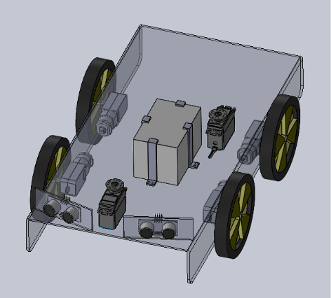
In week 4 I spent time working on making a simple 3D model of the base plate and I started to add components, and their connections. Besides the modeling work I did research into the skid teering mechanism we are going to use, and how this can be optimal (wheelbase distances, etc.). Next week will be adding the aditional components and making a 3D base model that is ready to be printed/cut.
Åsmund Wigen Thygesen
This week I was supposed to get the GPS system up and running and start work on the motion control system. This was originally Sulafs task, but due to its necessary integration in the motion control system, as positional feedback, I ended up taking over the task.
When we were shown the GPS system(Swift navigation Piksi v2) we were briefly told what it was and naively assumed it worked a specific way based on that. We thought it was an entirely independent system that would track its own local basestation.
Pretty shortly after looking into how to get it set up it was pretty obvious that this is not how it works. The modules still rely on regular GPS and can therefore not provide an accurate position indoors, which is where we need to be able to demonstrate our system. If you wanna read more about how they work, check here: https://support.swiftnav.com/support/solutions/articles/44001850808-understanding-gps-gnss-rtk-technology
I still tried setting it up inside, hoping it could work, just with less accuracy, but maybe enough for our purposes, but was unable to get it working at all inside.
This means we cannot use the GPS for knowing the position of the robot and need to discuss how to move forward during our next meeting.
Not being able to move forward with the GPS, I started setting up the class for the motion control system. This will be responsible for moving the robot to specific positions, the current plan is to do this with a feedback loop. Essentially “Rotate robot until desired angle is reached” and “drive robot forward until the desired position is reached”. These functions can be combined into a “go to this position” which the overarching navigation system will interface with.
I got some of the basic stuff set up, and should be able to do more next week, but with the current unknowns in the project it is hard to know where to start.
Rick Embregts (Electronic engineer)
This week I was busy with getting a detailed view of the electrical system. This way we know what components we will need and how they will connect to each other. The form of the overview for now is a Table of all components and ports. Next week the first schematic will be made to complete the overview. See a small part of the table below to get an idea how it looks.
| Component | Pin | Description | Component (Pin) |
| Spray | M+ | Positive pole motor | – |
| M- | Negative pole motor | – | |
| Drive (1t/m4) | M+ | Positive pole motor | Motor Controller (M+) |
| M- | Negative pole motor | Motor Controller (M-) | |
| ENC-B | B signal encoder | Raspberry Py (Pin7, 10) | |
| ENC-A | A signal encoder | Raspberry Py (Pin8, 12) |
Darkio Luft (Data Engineer)
I ran some tests last week and found that the YOLOv11n model was too heavy for our Raspberry Pi 4 to handle. So, we’ll be using YOLOv8n for the neural network implementation instead. I’ve also researched other projects that used YOLOv8n for weed detection to use as a reference for our own project.
Overview
The navigational part was originally my part; however, it seemed impossible for Åsmund to partake in the task of controlling the movement of the motors (wheels) without overtaking some of the navigational part in the process, seeing there’s a very thin line between his task (the control system and motion control of wheel), and my task of navigation. So, we split it even further, with me focusing on finding a way to navigate obstacles.
That is the reason why I started looking at the ultrasonic sensors we need for obstacle detection in our AROWEEK robot this week. In addition to that, I looked at possible obstacle avoidance. I went through a lot of personal notes and research this week (the research was kind of information dense), so let’s break it down into different parts to make the blog more digestible. As usual, I had a guideline of questions to follow, and to know if I had hit the goal for this week.
The Guideline Questions
- What did I learn about this topic, any updates from last week? (Theoretical part)
- What are the different components needed? (Physical components)
- How will the components function within our system? (Practical application)
- Code update? (Snippet of relevant code)
Theoretical Part
For starters, to summarize what I did last week, I had looked into the GPS system we were offered by the teachers at school. And while we realized that the GPS was a very tempting and viable option for outdoor activity for the AROWEEK robot, we still have to show the demo of our finished product in Dronesonen, which is a controlled, indoors environment. So, by having to do it inside it would affect the GPS’s effectivity. Though all hope was not lost, because we decided to go with another navigational system from the three I had suggested to the group in week 1&2: that is with the wheel encoders with the IMU (the third option I had suggested, but with no need for the GPS, as I had also included it as an optional feature).
Instead of the GPS, the group wanted to tweak it so that we use the compass from the IMU in combination with the wheel encoders. The reason I had included the GPS to begin with in that option was for a more realistic approach if this project was to ever be implemented in real, larger agricultural fields outdoors. The GPS would pinpoint the accuracy well outdoors. So while we could not use the RTK GPS in our demo version in this course due to environmental constraints (needing the demo to be shown indoors, in Dronesonen), it is important to keep in mind that it could be incorporated in the AROWEEK robot with the resources of larger companies if the idea was ever to get adopted by them.
Practical Application
Now that we’ve locked in the navigation system—wheel encoders paired with the IMU compass—it’s time to look at how obstacle detection fits into the bigger picture. Since my focus this week was on navigating obstacles, I dove into how ultrasonic sensors could help us achieve that. These sensors will be mounted on the front of the robot only, to detect nearby objects and trigger avoidance maneuvers. We already had a type of ultrasonic sensors here at USN campus, so luckily, we did not need to order any parts.
Now, for the obstacle detection, the train of thought was quite straightforward, this is what I wanted it to do: if the robot detects an object within a certain threshold distance it will pause, recalculate its path, and reroute around the obstacle before continuing on its path. This would keeps the robot from crashing into anything while maintaining full coverage of the terrain.
Ultrasonic sensors are ideal for this because they’re inexpensive, lightweight, and reliable in indoor environments like Dronesonen. They don’t require complex calibration and can be easily integrated with the Raspberry Pi 4, which we’re using for processing.
Physical Components
So far, here are the components we are using so far, and what we need them for.
- One camera: for identifying weeds.
- One ultrasonic Sensor: Detect and avoid obstacles in real time
- A spray: A spray that can be triggered when a weed is detected with the AI training model (with the camera).
- Raspberry Pi 4: Our central processor that handles sensor input and decision-making, including the AI trained model.
- Motor Driver with wheel encoders: To control wheel movement based, and the wheel encoders for tracking distance traveled
- IMU: For orientation and compass heading
These components will work together to allow the robot to move intelligently through the terrain, detect obstacles, and adjust its path accordingly, all without GPS or LIDAR.
Code Update
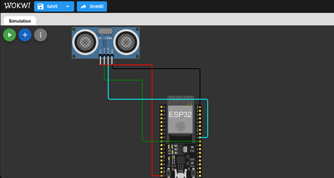
I’ve started prototyping the obstacle detection logic using Python. But it is a lot harder to write a code when I cannot physically see the changes and results of the code in real time, seeing we don’t have a prototype yet. So, I had to mostly rely on a simulated version of the Rasberry Pi and the ultrasonic sensor online. But because the website options were quite limited, I found a free version that also had options most similar to the Raspberry Pi 4 in terms of processing power, that being ESP32. The ultrasonic sensor by default (the only one available as a component was the HC-SR04, which after research I found it was an applicable as a test prototype option for the code. The website was quite straightforward, called WOKWI. I only needed to plug the right pins to the ultrasonic sensor and it would provide an obstacle for the ultrasonic sensor to detect, since this week only detection is in focus.
The set up visually in WOKWI:
The code with comments:
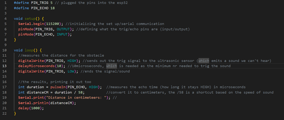
This is just the beginning of the code, but it’s already helping me visualize how the robot will respond to its environment. Next week, I’ll work on integrating this with the motor control system Åsmund is developing, which hopefully will propel us further in the project timeline.
Summary and Reflection
This week was dense, but productive. We’ve officially moved past the theoretical phase and into real implementation, in a way. The decision to drop GPS and rely on onboard sensors was a turning point (it made the project more grounded and achievable, the goal of the project feel a lot closer now). I’m excited to see how the obstacle detection system evolves as we start testing in Dronesonen as well.