This week, our group continued the develoment of the RC motorcycle. The overall goal of this week was to start developing a minimum viable product that can drive forward and backwards, before moving on to more advanced features such as steering and self-balacing.
To ensure a shared understanding of the system design, the group worked on drawing UML diagrams, creating sketches in SolidWorks and simulating how the system would look the choosen electronic components in Wokwi. These activities allowed us to evaluate feasibility and identify potential issues in at an early stage.
Looking forward the next steps will be to finalize the wiring of the electronic componets needed for the minimum viable product, develop the necesarry code for the movment of the motorcycle and draw a design and print the chassis of the motorcycle.
Salim:
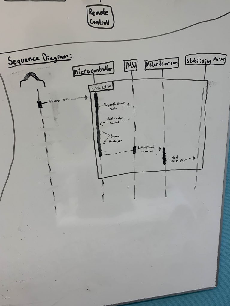
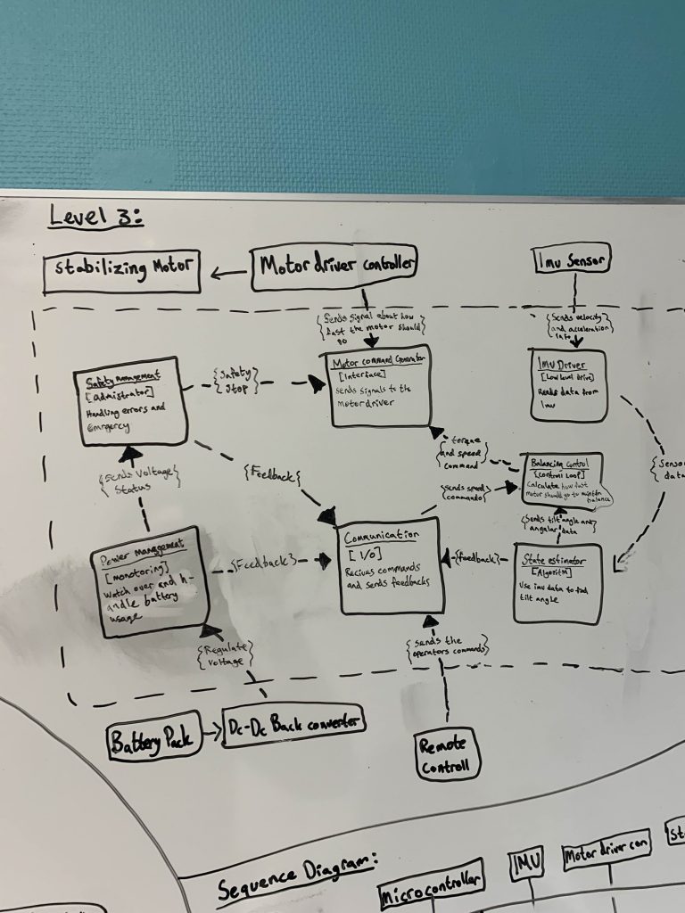
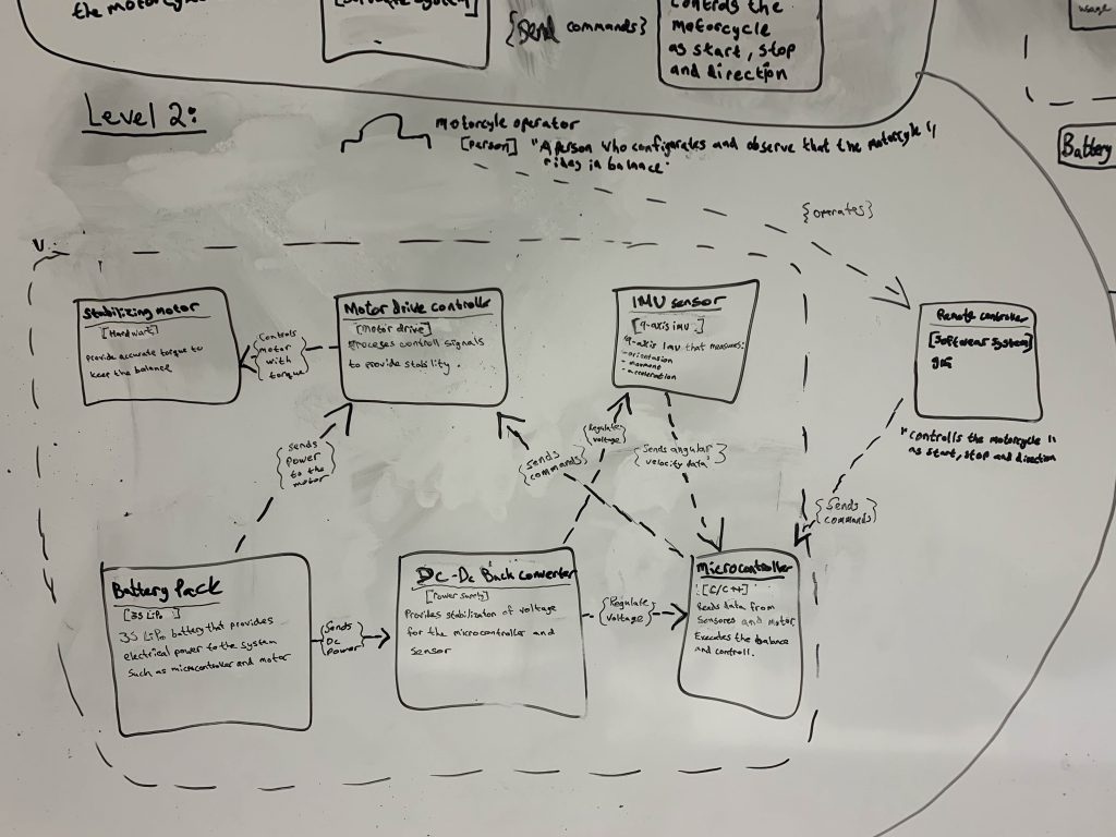
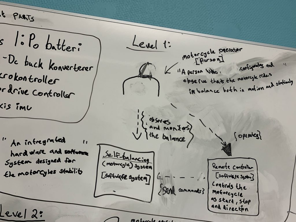
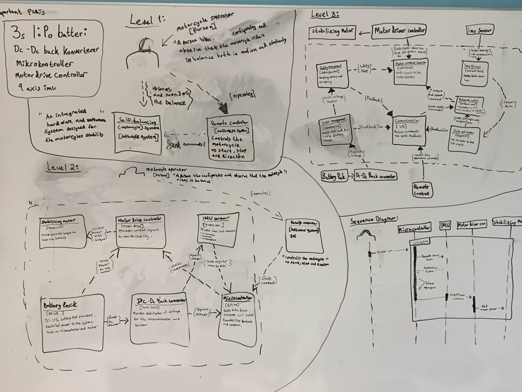
As part of this project, I started by creating a visualization of our system to demonstrate its functions and functionality. Therefore, I developed both a C4 model and a sequence diagram.
The sequence diagram shows how the microcontroller interacts with the IMU, motor driver, and stabilizing motor when the system is powered on. It illustrates the flow of operations, such as requesting sensor data and sending torque commands to the motor.
The C4 model represents the system at different levels, explaining how the hardware and software components work together. It provides a clear visualization of the system’s structure and behavior, making the development process easier and more efficient.
Meron:
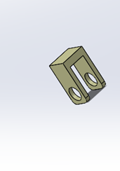
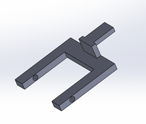
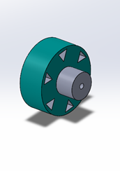
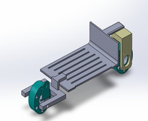
This week I began working on the first phase of building the motorbike protype. The goal of this phase is to ensure that the motorbike can move forward and backward. To support this. I have been working in SolidWorks, where I designed the key structural parts including the chassis wheels, and the bear arm. Thes parts are now prepared for 3 D printing which will allow us to assemble the basic prototype. Once the mechanical setup is complete the data engineering team will be able to start their work on programming controlling the movement of the bike. By completing the fundamental
Mohammed A:
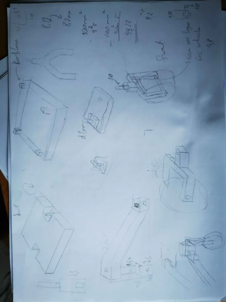
I drew conseptes of moter bike for face 1 for the presentation, focosuing primerly at the components and electronics that will be places on the bike.
as mentioned previously i wanted the body of the bike be big for the components and have multiople levels, for each seperate electronic-piece. In addition we planned to build wide wheels for the first faese so that we can focues on building the bike and not the stability of it.
In this I focused on the 3D parts to be easily printed and build with focus on the motor to be in the right place and electronics, in this concept the primely focus was for the bike to move back and forward without steering right or left
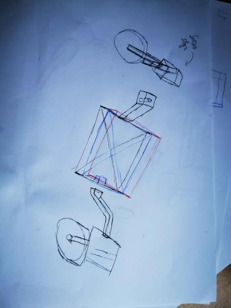
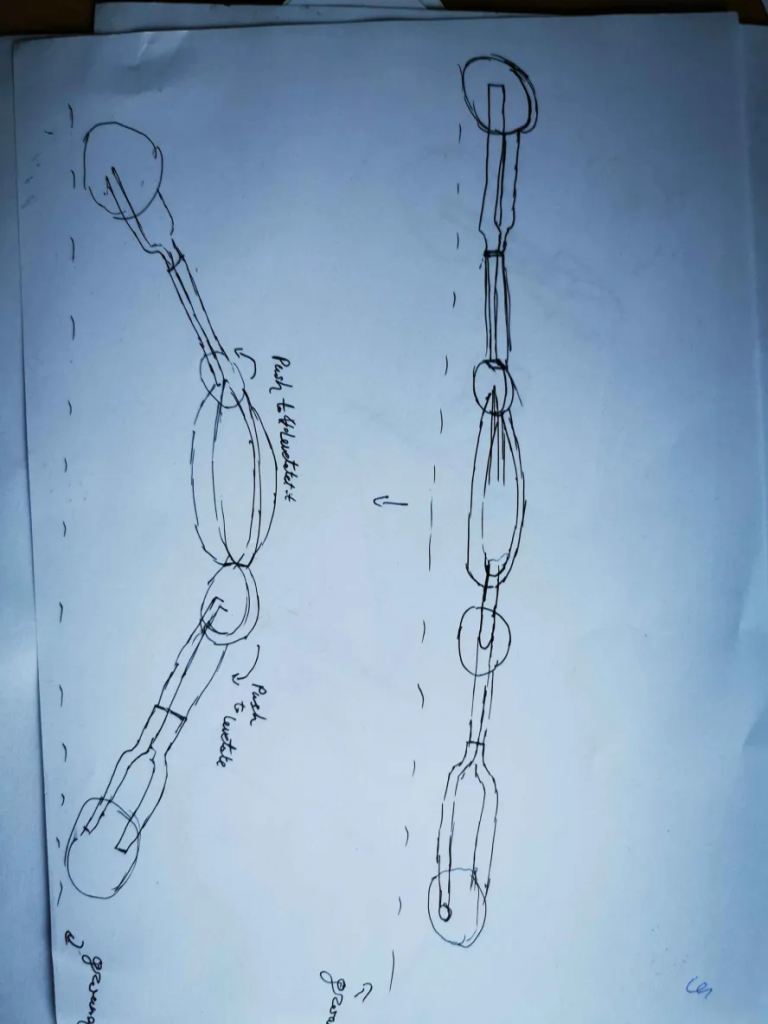
This is a concept/idea for faese three, the group hasn’t yet decided but the idea came from our teacher. The thought behind it is that when bike is stationery, the main body will be lower itself to the ground so that it doesn’t wobble, when its on the move it will raise itself up from the ground and drive. In addition, while it raises itself up arms can bend to until they are parallel to each other which then will make momentum wheel work more to balance it since the closer the wheels are together the more difficult it is to balance.
Muhammed Ø:
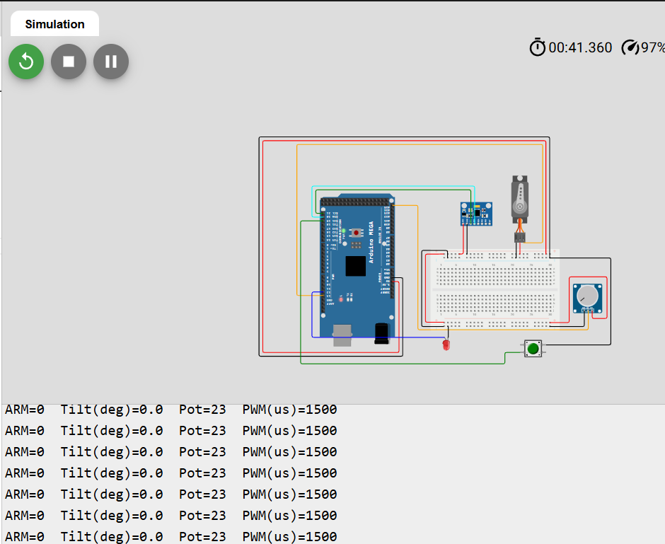
This week i focused on the simulation side of the project. I set up our system in Wokwi with the components required for the minimun viable product and started experimenting with the imu sensor provided in wokwi, this was done to ensure understanding of how the components would work together, and how we could integrate the sensor with the control system.
this picture shows when the system isnt armed, you can see the value of the potentiometer, the tilt degree of the imu sensor, and if the system is armed or not
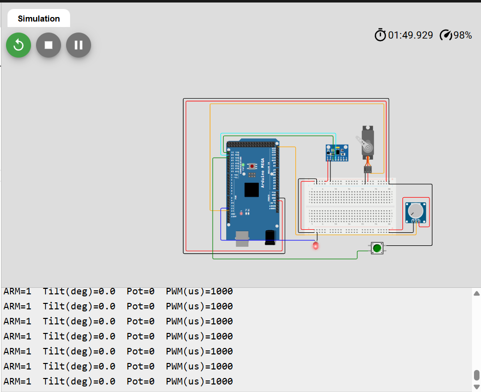
this picture shows when the system is armed, showing the servo spinning towards the right
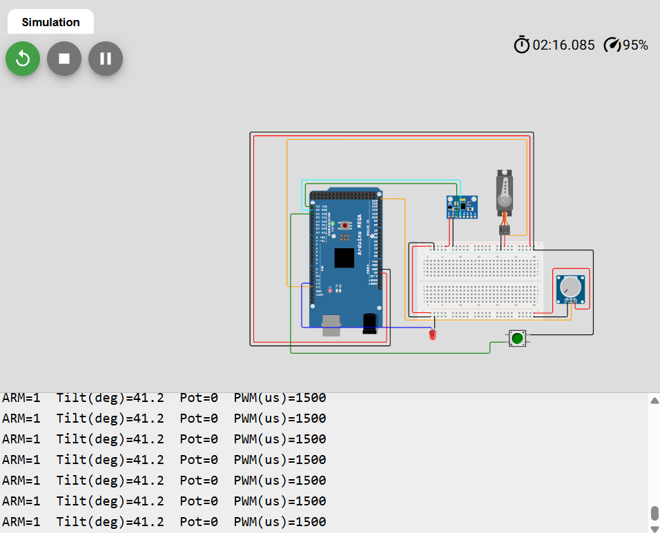
this picture shows when the imu is tiltet to 41 degrees and the system is armed but the servo isnt spinning
#include <Wire.h>
#include <Adafruit_MPU6050.h>
#include <Adafruit_Sensor.h>
#include <Servo.h>

Adafruit_MPU6050 mpu;
Servo motor; // stand-in for ESC/motor i Wokwi

// Pinner (Arduino Mega)
const int PIN_SERVO = 13;   // servo
const int PIN_POT   = A15;  // potmeter
const int PIN_ARM   = 19;   // knapp til GND, INPUT_PULLUP
const int PIN_LED   = 12;   // status-LED

// Parametre
const int NEUTRAL_US = 1500;
const int MIN_US     = 1000;
const int MAX_US     = 2000;
const float TILT_FAILSAFE_DEG = 35.0;

unsigned long lastPrint = 0;

float calcTiltDeg(sensors_event_t &accel) {
  float ax = accel.acceleration.x;
  float ay = accel.acceleration.y;
  float az = accel.acceleration.z;
  float tilt = atan2f(sqrtf(ax*ax + ay*ay), az) * 180.0f / PI;
  return tilt;
}

void setup() {
  pinMode(PIN_ARM, INPUT_PULLUP);
  pinMode(PIN_LED, OUTPUT);
  digitalWrite(PIN_LED, LOW);

  Serial.begin(115200);
  Wire.begin();

  if (!mpu.begin()) {
    Serial.println("MPU6050 ikke funnet. Sjekk kobling!");
    while (1) { digitalWrite(PIN_LED, !digitalRead(PIN_LED)); delay(200); }
  }

  mpu.setAccelerometerRange(MPU6050_RANGE_4_G);
  mpu.setGyroRange(MPU6050_RANGE_500_DEG);
  mpu.setFilterBandwidth(MPU6050_BAND_21_HZ);

  motor.attach(PIN_SERVO);
  motor.writeMicroseconds(NEUTRAL_US);

  Serial.println("Klar: pot=A0, knapp=D2 (hold for ARM), servo=D9, MPU6050 på A4/A5.");
}

int potToPWMus(int potRaw) {
  long us = map(potRaw, 0, 1023, MIN_US, MAX_US);
  return constrain((int)us, MIN_US, MAX_US);
}

void loop() {
  int armed = (digitalRead(PIN_ARM) == LOW);
  int pot   = analogRead(PIN_POT);

  sensors_event_t accel, gyro, temp;
  mpu.getEvent(&accel, &gyro, &temp);
  float tiltDeg = calcTiltDeg(accel);

  bool failsafe = (!armed) || (tiltDeg > TILT_FAILSAFE_DEG);

  int cmd_us = NEUTRAL_US;
  if (!failsafe) {
    cmd_us = potToPWMus(pot);
  }

  motor.writeMicroseconds(cmd_us);
  digitalWrite(PIN_LED, failsafe ? LOW : HIGH);

  unsigned long now = millis();
  if (now - lastPrint > 200) {
    lastPrint = now;
    Serial.print("ARM="); Serial.print(armed);
    Serial.print("  Tilt(deg)="); Serial.print(tiltDeg, 1);
    Serial.print("  Pot="); Serial.print(pot);
    Serial.print("  PWM(us)="); Serial.println(cmd_us);
  }
}
Some of the components used in the simulation are not the exact ones we will be using in the final product, this is due to the limited library available for free users on Wokwi. In the simulation we used a MPU6050 as a imu sensor, a servo motor to represent a motor, a potentiometer to that functions that functions as a bi directonal throttle, a push button to act as a the arming switch (pressed = system on, released = system off), and an LED to indicate when the system is active.
The code demonstrates how the IMU sensor integrates with the motor and the overall controll system. if the system register a tilt of 35 degrees it triggers the failsafe which doesnt allow for the servo to spin.