This week, our group has started preparing the presentation for the project. We discussed the key points we want to include, such as the problem domain, our project structure, and the technical solutions we have developed. Each member has taken responsibility for different sections, and we have begun drafting slides and organizing the flow so the presentation clearly explains both our process and results.
When discussing how to control the wheels, sensors and the arm of the robot we ran into the problem of having enough connections. Since the motors with built in encoders have 2 more connections each, the driver expansion board v2 has enough pins for the wheels and sensors but not for controlling the arm. so we want to use two microbits. one for controlling the wheels and sensors and one for the robotic arm. These will communicate over bluetooth.
Theo:
On my way to understanding how to interact with the sensor. I follow different steps. But first I had to set up an auspicious environment to speak with the micro:bit with platformio and VS code.
platformio.ini : [env:bbcmicrobit_v2]
platform = nordicnrf52
board = bbcmicrobit_v2
framework = arduino
upload_protocol = cmsis-dap
lib_deps =
adafruit/Adafruit PWM Servo Driver Library@^3.0.2
adafruit/Adafruit BusIO@^1.17.2
adafruit/Adafruit Microbit Library@^1.3.4
adafruit/Adafruit GFX Library@^1.10.13
Adafruit Microbit
https://github.com/SpulberGeorge/EasyUltrasonic.git
lib_ldf_mode = deep+
My first step was to be sure that I can communicate well with micro:bit by printing a smiley on the led. Then add a sad face that changes when we click the A button. So later I can use this 2 face to know how far somethings is from the sensor.
First code :
#include <Arduino.h>
#include <Adafruit_Microbit.h>
Adafruit_Microbit microbit;
const uint8_t PROGMEM happy_bmp[] = {
B00000,
B01010,
B00000,
B10001,
B01110
};
const uint8_t PROGMEM sad_bmp[] = {
B00000,
B01010,
B00000,
B01110,
B10001
};
const int BUTTON_A_PIN = 5;
bool isHappy = true;
unsigned long lastToggleMs = 0;
const unsigned long debounceMs = 250;
void setup() {
microbit.begin();
microbit.matrix.begin();
pinMode(BUTTON_A_PIN, INPUT_PULLUP); // pin avec pull-up (LOW = appuyé)
microbit.matrix.show(happy_bmp);
}
void loop() {
int state = digitalRead(BUTTON_A_PIN);
if (state == LOW && (millis() – lastToggleMs) > debounceMs) {
// appui détecté -> toggle
isHappy = !isHappy;
microbit.matrix.show(isHappy ? happy_bmp : sad_bmp);
lastToggleMs = millis();
}
delay(10); // petit délai pour alléger la boucle
}
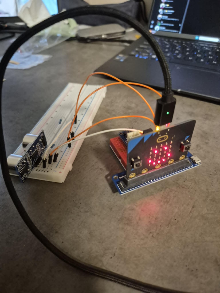
Then I test with some electronics, with a basic assembly and a code to try changing the face depending on the distance from the sensor.
Seconde code :
#include <Arduino.h>
#include <Adafruit_Microbit.h>
#include <EasyUltrasonic.h>
Adafruit_Microbit microbit;
const uint8_t PROGMEM happy_bmp[] = {
B00000,
B01010,
B00000,
B10001,
B01110
};
const uint8_t PROGMEM sad_bmp[] = {
B00000,
B01010,
B00000,
B01110,
B10001
};
#define TRIG_PIN 1
#define ECHO_PIN 2
EasyUltrasonic ultrasonic;
const float THRESHOLD_CM = 10.0;
unsigned long lastPrint = 0;
void setup() {
Serial.begin(115200);
microbit.begin();
microbit.matrix.begin();
microbit.matrix.show(happy_bmp);
ultrasonic.attach(TRIG_PIN, ECHO_PIN);
}
void loop() {
float distance = ultrasonic.getDistanceCM();
if (millis() – lastPrint > 400) {
Serial.print(“Distance (cm): “);
Serial.println(distance);
lastPrint = millis();
}
if (distance > 0 && distance < THRESHOLD_CM) {
microbit.matrix.show(sad_bmp);
} else if (distance > 0) {
microbit.matrix.show(happy_bmp);
} else {
}
delay(150);
}
But for now, I didn’t succeed.
Sondre:
This week i finally got the car to move, and that was such a good feeling. The big breakthrough came when i found out that PlatformIO already had the Adafruit library. Before i was trying to write alot of the code myself, but with the library i didn’t need to do all that hard work from scratch. It made things alot easier and i could just focus on getting the robot to actually drive.
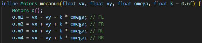
I also tried to make the project more organized. I put code into the include folder and the lib folder, so that the main file was short and easy to read. In include i keep the schematic for the mecanum robot, basically the formulas for how each wheel should move. For example the “mecanum” function calculates how much speed to give each motor:
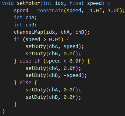
In lib i keep the code for the micro:bit board. That file knows which control channels belong to which motor and sets the duty cycle. For example the “setMotor” function decides which direction and how fast each motor should spin:
That means my main.cpp can stay really simple and just call nice functions like move_forward(0.8) or turn_left(0.8). For example:
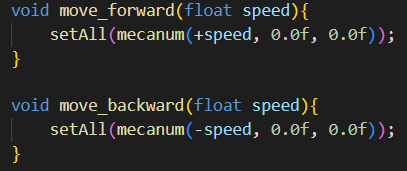
So the main loop is easy to read, almost like giving instructions:
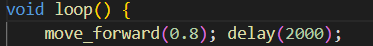
Making functions for the different movements turned out to be pretty easy with this setup. Now i can just call forward(), backward(), strafe, or turn, and the car does it. Testing and changing stuff is way faster now. This week really felt like a big step forward.
Robin:
The Arm
I’ve started modeling a robotic arm designed to transport packages from point A to point B. To begin, I searched online for references to help me with the 3D model’s design.
Internet Research
Here is what I found:
https://www.hiwonder.com/products/mecanum-wheel-chassis-car?_pos=32&_sid=ef923f775&_ss=r
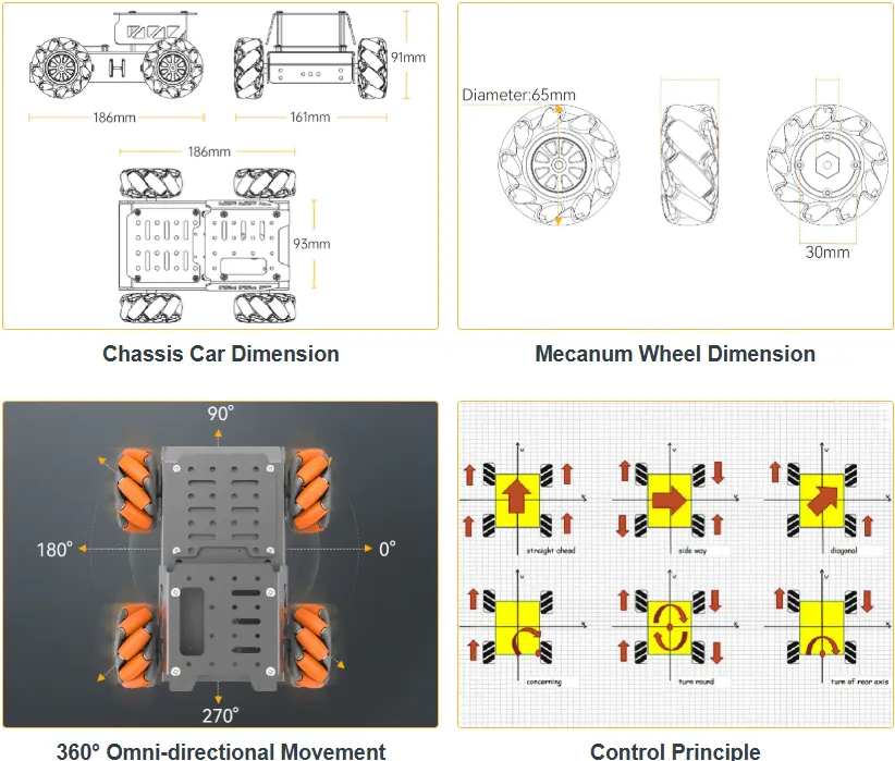
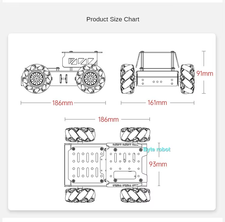
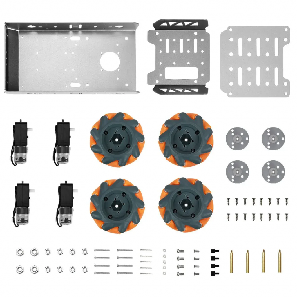
I used the second image to create the robot’s supports. Using the dimensions shown in the size chart, I was able to scale the image to 1:1 in my 3D software, Fusion 360.
- I imported the image onto my 3D plane.
- I used the provided dimensions for scaling.
- I verified the calibration by measuring other parts of the plan, which will ensure that my models have the correct proportions
Support Design
I started by modeling the top plate of the car from an image.
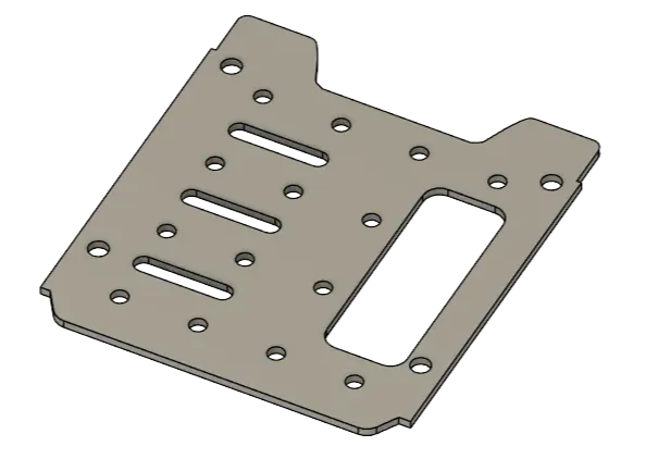
Now we can move on to manufacturing the support model.
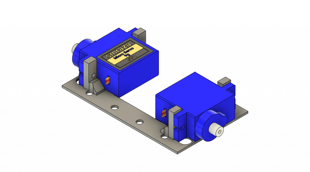
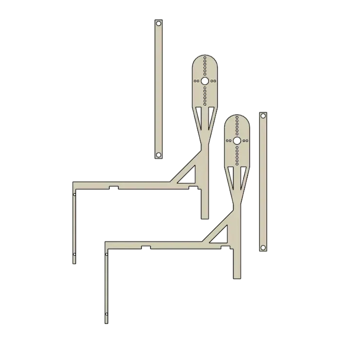
Arm Design
Next, I moved on to modeling the arm.
Free CAD Designs, Files & 3D Models | The GrabCAD Community Library
Here is the first version of the arm :
3D-Printed Parts:
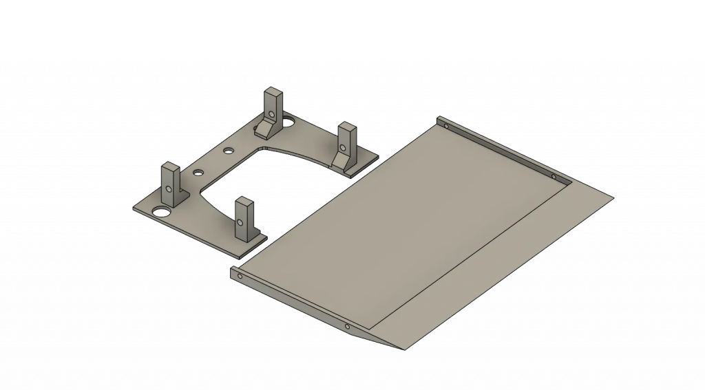
Laser-Cut Parts:
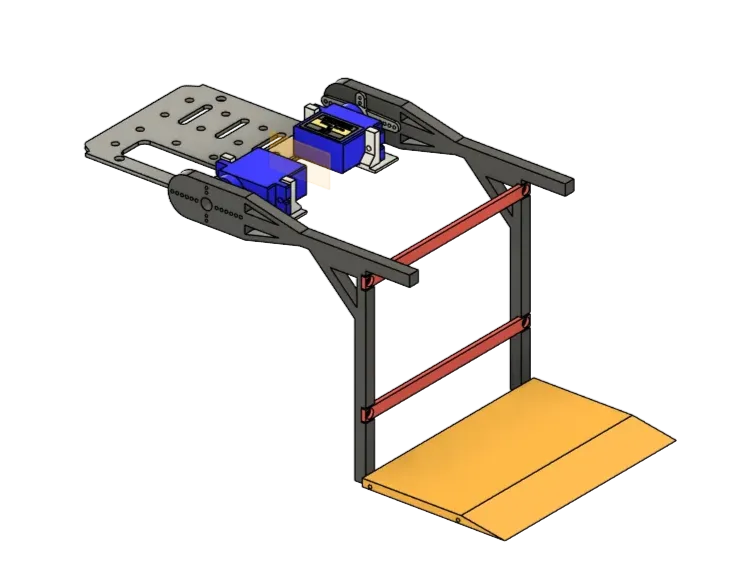
Chassis Modeling
Since I had some extra time, I also modeled the car in 3D. This will be useful for visualizing future mechanical improvements and testing new designs.
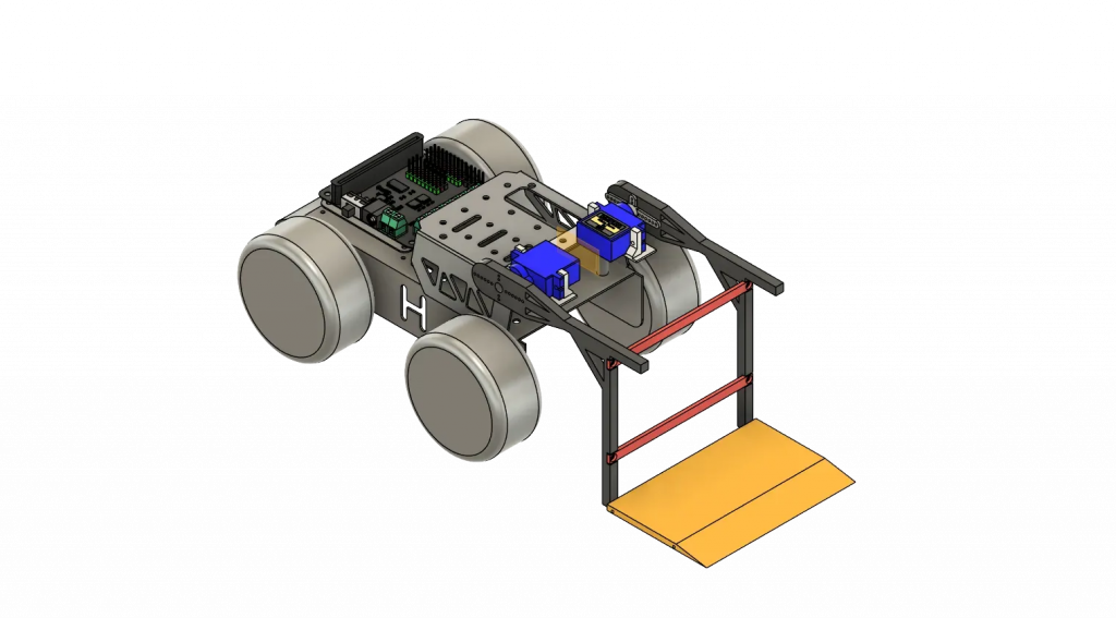
Here is the result of the chassis model.
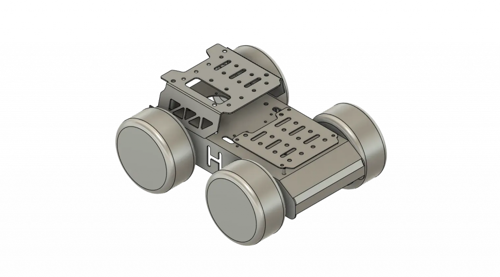
3D model of everything
Anette:
This week I have been working on the project structure. This Monday we discussed and finalised the details of our project. This is what we came up with, details might change:
- microbit 1 (original): pickup mechanism + motors
- microbit 2: distance sensors
Where exactly the robot will operate
- The car will operate in a maze with a set path. We need to figure out the width and length of the path in order to know how far from the wall the car needs to be before turning. We will check this on Monday due to not having access to the cave before now.
How it will behave in the set space
- The car will travel down a straight path while measuring the sides in order to stay in the middle, and measure the front to see where the path takes a turn. When reaching an end the car will measure which side the wall is on in order to know what way to turn. Then it will drive close enough to turn while monitoring the distance from the sides. When reaching a wall with nowhere to turn the car will know this is the box and proceed to the pickup process. Then it will keep maneuvering its way to the end of the path.
Where is the delivery point
- For now the delivery point will be at the end of the path, but we might expand on this later
Order of operations
- Movement
- Check for wall in front
- Decide if it is a box or wall by using the side sensors to look for a side without a wall
- If box, reverse a bit, lower arm and pick up box
- finish the path
- set box down at the end of the path
We also started working on the presentation by looking through the points on canvas, seeing what we could do and what we need to get done.