Wang
Zephyr
This week I tried to set up the Zephyr environment. I started by downloading CMake, Ninja, and Git. Then I managed to get west working so I could build the firmware for the micro:bit. winget install Kitware.CMake<br>winget install Ninja-build.Ninja<br>winget install Git.Gitpip install westwest init -m <https://github.com/zephyrproject-rtos/zephyr> Then I created a CMakeLists.txt, prj.conf, and main.c. Then I tried to run this code.
#include <zephyr.h>
#include <sys/printk.h>

void main(void)
{
    while (1) {
        printk("Hello World from micro:bit v2!\\\\n");
        k_sleep(K_SECONDS(1));
    }
}
But I ran into problems when trying to run it. west build -b bbc_microbit_v2 — everything went fine until the end where it seemed like it couldn’t find #include <zephyr.h> and #include <sys/printk.h>. That’s as far as I got with this this week. micro:bit V2 — Zephyr Project Documentation
The goal last week was to get the car to drive forward, but that failed with the Arduino code we tried. However, we succeeded by using https://github.com/DFRobot/pxt-motor and Microsoft MakeCode for micro:bit. In real-time systems, we got the car to move forward and backward and turn a bit using ADA and the example code available at https://github.com/aiunderstand/Ada-Embedded-Project-MicroBitV2. So for this week, I’m unsure what the goal should be, other than maybe continuing to try to set up the Zephyr environment and see if I can get the car to move using it.
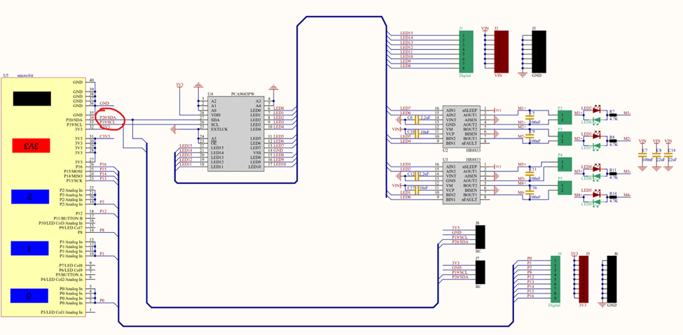
But something that has been figured out is that the board we’re using DFR0548 only uses 2 pins to communicate with the motors, pin 19 and 20.
Oskaras
For this week:
This week our goal was to get the car to drive forward. We spent some time figuring out how to communicate with the micro:bit. At first, we tried to apply Arduino logic to it with different pins, but towards the end we found the datasheet for the micro:bit driver board. There we saw that we only need two connections, SDA and SCL, to communicate with the rest of the board.
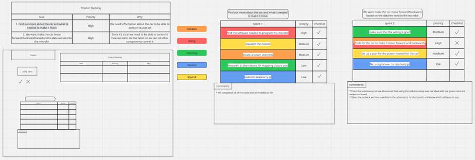
For better overview, I also created a new scrum board, which just gives a clearer view of the whole process and makes it much easier to present.
Henning
For this week:
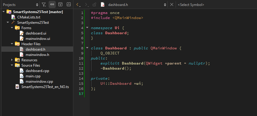
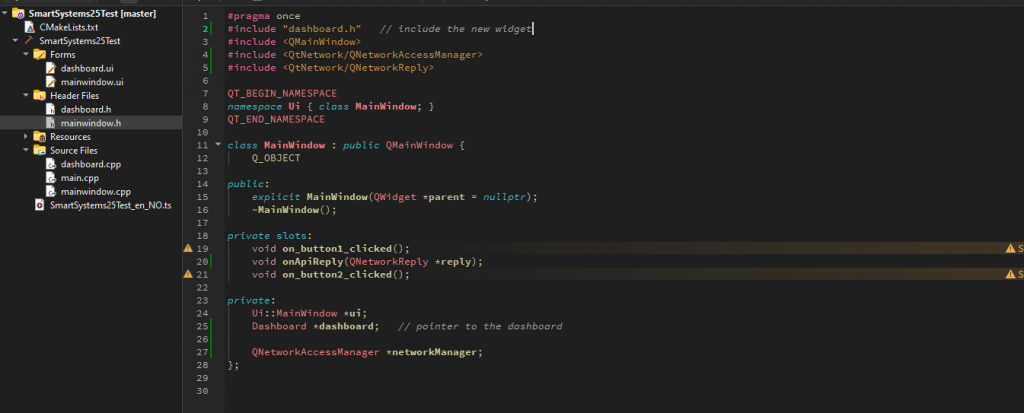
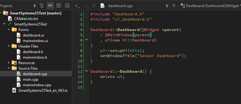
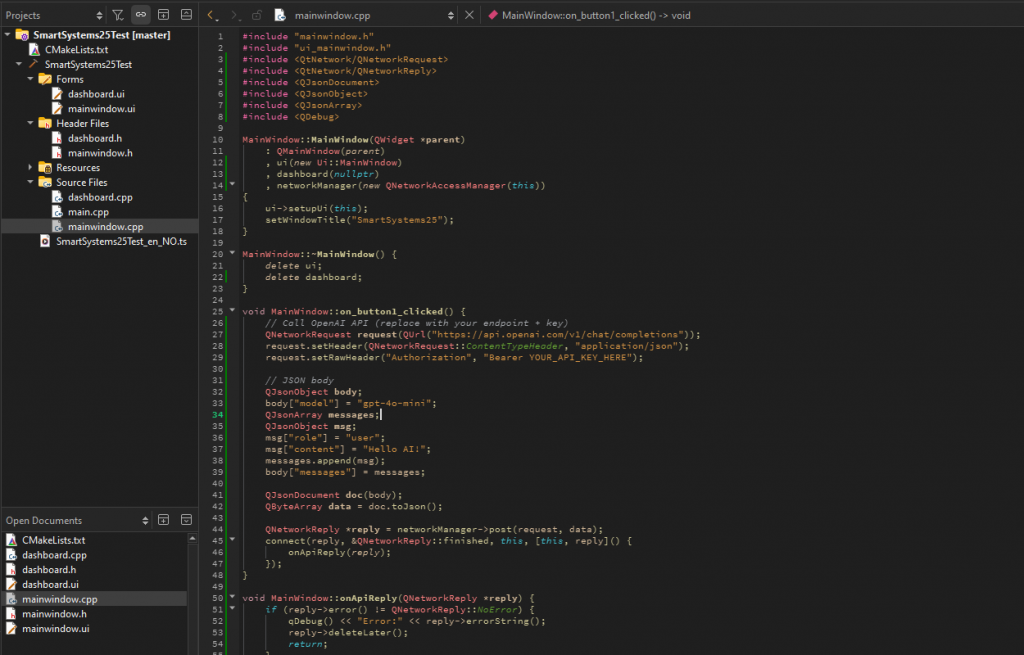
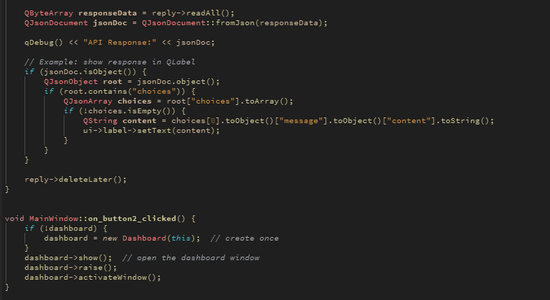
I have sadly been a little sick, so my work got limited. I did manage to get some work and improvements done before i took some time off. What i have done so far is that i have extended the buttons on the GUI further. So for the button “show data”, i have now coded so when pressed, it will open a new dashboard where our data will be shown.
The other button that i am currently working on is the “Connect to AI” button. Where i do think i have the majority of code setup, and that i would just need to add an API Key for it to work.
Here you can see the progress in coding done so far:
Progress for next week:
I will do more research on API Keys and how to set it up securely. Secondly its going to be discussed in the group of which AI we would want to focus on. For the “Show Data” button, i will read more on the sensors and how i could implement those data results into the dashboard i have created.
Øivind
Learning by failing? A lesson learned from week five is that it can be quite costly. This week we started by finally craft a code that seemed to work with the motor board. I take pride in the fact I contributed to that process. Nevertheless. Me, myself, I take full responsibility. But thankful that the others present in Dronesonen, who witnessed me mismanage the power supply witch led me to fry at least one critical part on the motor board. Saw that the power supply was set to the correct 5V when connected. I have not come to an conclusion about what went wrong, but I’m curious so I will be humble enough too seek answers on that episode. Monday Steven took me to a lab to scout for parts needed for our project. I really enjoyed the chance to see the car that was referenced the first lecture. Makes it somewhat feel pointless to build our project. But then again, not really. I am excited with this project. Steven gave me a high-quality DC-DC step-down converter we can borrow for the project, along with a voltage tester with buzzer I might find useful or fun to implement. I’ve still not decided for the BMS. It has not been the most productive week, but maybe I just don’t recognize the small steps I have done in this process.
Zardasht
After trying many different methods to get the Raspberry Pi camera working, I eventually had to reset the Raspberry Pi and reinstall the necessary packages and updates. In the end, I managed to get the camera running with the help of AI. I also experimented with some code to make the camera smarter, such as color recognition and shape recognition. However, these features didn’t seem to work properly. In addition, I tested an ultrasonic sonar, but things didn’t go as planned—although I ran the code, no values appeared on the screen. I’ve been working on this project for several days, spending about two hours each day. Even though some things didn’t work as expected, I found it exciting and educational to work with the Raspberry Pi.